
Пролет мостового крана и высота подъема — это два параметра компоновки, которые определяют все остальное в конструкции заводского крана. Пролет — это горизонтальное расстояние между осевыми линиями рельсов взлетно-посадочной полосы; высота подъема (Также называемый ходом крюка) — это вертикальное расстояние, на которое крюк может подняться от своего самого нижнего до самого верхнего положения. Если допустить ошибку на этапе проектирования, вы либо потратите бюджет на конструкцию впустую из-за излишнего количества стали, либо — что еще дороже — обнаружите в день монтажа, что ваши грузы не смогут пройти мимо оборудования под крюком.
Перед планировщиками и менеджерами по оборудованию на производстве стоят два конкретных вопроса: Какой пролет мне следует указать, учитывая расстояние между колоннами в моем здании? И Какова необходимая высота подъема, учитывая полезную высоту потолка в моем здании? Оба расчета на первый взгляд кажутся простыми, но каждый из них скрывает множество вычетов — выступы торцевой балки, высота корпуса подъемника, расстояние перемещения груза крюка, верхний безопасный зазор — которые в сумме дают 700–1000 мм или более “потерянного” пространства, которое редко указывается в стандартных статьях.
В этом руководстве пошагово рассматриваются оба варианта расчетов с использованием действительных чисел, а затем показано, как меняются арифметические действия для однобалочных и двухбалочных конфигураций, и что делать, когда высота потолка действительно невелика.
Получить цитатуПонимание пролета и высоты подъема мостового крана.

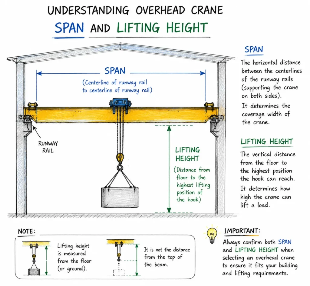
Что означает «протяженность» — и чем она не является.
Пролет мостового крана — это расстояние между центрами двух рельсов, а не ширина здания и не длина балки моста. Именно этот размер напрямую определяет, какую часть площади вашего здания может обслуживать кран, и это первый параметр, который поставщику необходимо указать, прежде чем он сможет предложить какие-либо другие варианты.
В принципе, зависимость от ширины здания проста: пролет равен расстоянию между центрами колонн здания минус удвоенное расстояние от центра колонны до центра рельса. На практике это смещение между центрами рельсов зависит от геометрии балок взлетно-посадочной полосы и конструкции кронштейнов, но для предварительного планирования обычно используется следующее эмпирическое правило:
Пролет крана ≈ Расстояние между центрами колонн здания − 1,0 м – 1,5 м
Таким образом, в цехе с колоннами, расположенными на расстоянии 18 м друг от друга, обычно можно установить кран с пролетом 16,5 м или 17 м, а не 18 м. Этот зазор не является потерянным пространством — это место, необходимое для балок направляющих, концевых упоров и минимального безопасного зазора в 100 мм с каждой стороны между концевыми балками и конструкцией здания, как указано в Правила проектирования кранов FEM 1.001 и GB/T 3811.
Что это означает для планирования: если ваш производственный процесс требует, чтобы крюк достигал каждой боковой стенки на расстоянии не более 500 мм, то расстояние между колоннами должно быть рассчитано с учетом крана, а не наоборот. На новых заводах расстояние между несущими колоннами должно определяться пролетом крана, а не корректироваться под уже заданную сетку.
Что означает высота подъема — и скрытые составляющие этого понятия.

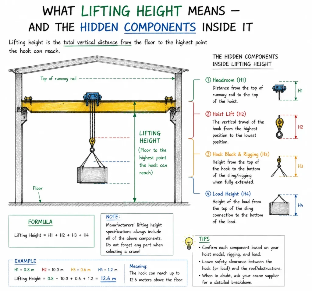
Высота подъема — нет Проще говоря, это вопрос: “На какой высоте от пола мне нужно поднять груз?” Это допустимый ход крюка, который может обеспечить кран, и он определяется путем вычитания ряда фиксированных механических и безопасных габаритов из полезной высоты потолка вашего здания.
Полная формула для расчета необходимой высоты потолка в здании (измеряемой от чистового пола до нижней стороны самой нижней кровельной конструкции или препятствующей балки) выглядит следующим образом:
Требуемая высота потолка = Необходимая высота подъема + Высота корпуса подъемника + Высота подхода к крюку (ход груза) + Максимальный безопасный зазор
Каждый компонент, пояснение:
- Необходимая высота подъема (H): Фактические рабочие требования — это высота, на которую ваш груз должен подниматься над уровнем пола, включая любые крепления или траверсы, прикрепленные к крюку.
- Высота подъемного механизма (h₁): Вертикальный размер самого подъемного механизма (тросового или цепного подъемника), измеряемый от крюка в самом верхнем положении до верхней части барабана подъемника или цепного кармана. Обычно он составляет от 560 мм до более 1000 мм в зависимости от грузоподъемности и типа подъемника; подъемники европейского типа с малой высотой подъема специально спроектированы для уменьшения этого размера.
- Подход с использованием крюка / перемещение с собственным весом (ч₂): Минимальное расстояние, на которое крюковой блок должен свисать ниже барабана лебедки даже в полностью втянутом состоянии, обусловлено геометрией узла крюкового блока. Обычно это 600–800 мм для канатных лебедок грузоподъемностью от 5 до 32 тонн; уточните данные по конкретной модели лебедки.
- Максимальный безопасный зазор (h₃): Минимальный зазор, необходимый между верхней частью моста крана и самым нижним элементом крыши или препятствием. В руководствах FEM и стандарте GB/T 3811 указано минимальное значение 200 мм; на практике часто используется значение 300–400 мм с учетом прогиба крыши и допусков при монтаже.
Пример расчета — однобалочный кран грузоподъемностью 10 тонн, пролетом 12 м:
Предположим, что на заводе расстояние от чистового пола до нижней стороны кровельных стропильных балок составляет 8,0 м, а технологический процесс требует подъема грузов на высоту 5,5 м над полом.
| Компонент | Измерение |
|---|---|
| Требуемая высота подъема (H) | 5 500 мм |
| Высота корпуса подъемника (h₁, эталонное значение) | ~763 мм |
| Метод Хука (h₂, эталонное значение) | ~683 мм |
| Максимальный безопасный зазор (ч₃) | 200 мм |
| Общая требуемая высота потолка | 7146 мм |
Доступная высота подъема составляет 8000 мм → 8000 − 7146 = 854 мм запаса. Высота подъема 5,5 м достижима в данном здании. Если бы для процесса потребовалась высота подъема 6,0 м, общая необходимая высота подъема достигла бы 7646 мм — все еще в пределах 8000 мм, но с запасом всего в 354 мм. Запасы менее 300 мм должны стать поводом для проверки подъемника на предмет малой высоты подъема.
Приведенные справочные значения h₁ и h₂ иллюстрируют метод расчета; фактические значения необходимо сверить с техническим чертежом конкретной модели подъемника, прежде чем окончательно определять высоту здания или заказывать кран.
Расчет пролетов: пошаговая инструкция для новых и существующих зданий.
Шаг 1: Определите расстояние между центрами колонн или доступную ширину направляющих.
При проектировании новых зданий на этом этапе консультант по кранам и инженер-конструктор должны согласовать свои действия до начала заливки колонн. Правильная последовательность действий такова: сначала определяется требуемый пролет крана → инженер-конструктор проектирует соответствующую сетку колонн → затем определяется ширина здания. Обратная последовательность — сначала определяется сетка колонн, а затем выясняется, какой кран подходит — является наиболее распространенной ошибкой при проектировании заводских зданий, и она обычно приводит либо к неоправданно узким пролетам, либо требует дорогостоящих конструктивных изменений.
Для существующих зданий измерьте расстояние между фланцами колонн с обеих сторон пролета, затем вычтите ширину балки направляющей и выступ кронштейна с каждой стороны, чтобы определить доступное расстояние между осевыми линиями направляющих. Это ваш максимально возможный пролет. Для получения подробных рекомендаций по стандартам классификации, регулирующим проектирование конструкций кранов, обратитесь к [ссылка на документ]. Классификация кранов по стандарту ISO 4301.
Шаг 2: Примените вычет за торцевую балку.
На мостовом кране с верхним расположением балки концевая балка выступает за осевую линию рельса с каждой стороны. Для однобалочных кранов половина ширины коробчатого сечения концевой балки обычно составляет около 130–150 мм; если добавить минимальный зазор в 100 мм, то с каждой стороны уменьшается примерно на 230–250 мм. Таким образом, обе стороны вместе уменьшают доступный пролет примерно на 460–500 мм от расстояния между рельсами.
Именно поэтому расстояние между колоннами в 12,47 м обычно обеспечивает пролет крана в 12 м, а не в 12,5 м.
Шаг 3: Подтвердите уровень балки взлетно-посадочной полосы и высоту ограждения.
Рельс взлетно-посадочной полосы располагается поверх балки взлетно-посадочной полосы, что само по себе увеличивает высоту конструкции снизу. Высоту рельса (обычно 40–95 мм в зависимости от типа рельса, например, от QU70 до QU100) плюс глубину балки необходимо вычесть из полезной высоты потолка перед расчетом доступной высоты подъема. Это часто упускается из виду на ранних этапах проектирования и приводит к потере 150–400 мм дополнительной высоты потолка.
Шаг 4: Сверка с таблицей размеров подъемника.
После определения предварительного пролета и высоты рельсов, примените формулу расчета высоты потолка из раздела выше, используя фактические размеры модели подъемника. Если результаты не совпадают, варианты — в порядке возрастания стоимости — следующие: (а) выбрать подъемник с низкой высотой потолка, (б) опустить уровень балки/рельса, если это позволяет конструкция, (в) поднять крышу или добавить приподнятый пролет в новом здании.
Расчет высоты подъема: сценарии с ограниченным пространством над головой и сценарии, определяемые технологическим процессом.
Ориентированность на процесс: вы знаете, какая высота подъема вам необходима.
Это более простой случай. Определите необходимую высоту подъема, исходя из технологических требований (самый высокий груз + зазор над самым высоким препятствием, которое он должен преодолеть), запустите формулу расчета высоты потолка и убедитесь, что высота вашего здания соответствует полученному результату. Если нет, то у вас проблема со структурой здания, а не с краном.
Полезная перекрестная проверка: возьмите требуемую высоту подъема, добавьте 2000 мм в качестве приблизительного запаса на корпус подъемника + подход к крюку + зазор (это консервативная оценка для большинства конфигураций канатных подъемников) и сравните с полезной высотой потолка вашего здания. Если высота здания меньше (требуемая высота подъема + 2000 мм), перед заказом необходимо провести детальную проверку с учетом фактических размеров подъемника.
Ограниченная высота потолков: потолок определяется вашим зданием.
Это более сложный и распространенный случай на существующих заводах. Здесь расчет производится в обратном порядке: начнем с доступной высоты потолка, вычтем фиксированные механические и предохранительные компоненты, а остаток будет достижимой высотой подъема.
Достижимая высота подъема = Доступная высота потолка − h₁ − h₂ − h₃
Используя те же эталонные значения, что и в приведенном примере: здание с полезной высотой потолка 7,0 м обеспечивает приблизительно 7000 − 763 − 683 − 200 = 5354 мм достижимая высота подъема при использовании стандартного тросового подъемника. Если для вашего процесса требуется 6,0 м, вам не хватает примерно 650 мм — и никакое предложение “крана большей мощности” не решит проблему. Решение заключается в использовании подъемника с малой высотой подъема (который сжимает h₁) или в смирении с меньшей рабочей высотой.
Конфигурации с малой высотой потолка: когда количество мест ограничено.
Когда требования к пролету и высоте подъема мостового крана противоречат ограниченному потолку здания, в рамках конфигураций мостовых кранов существуют три варианта проектирования:
Канатная лебедка с малой высотой подъема: Переработанная геометрия барабана и направляющей троса позволяет уменьшить высоту корпуса лебедки на 200–400 мм по сравнению со стандартной лебедкой той же грузоподъемности. Voitto Кран с малой высотой подъема Используется этот подход, охватывающий грузоподъемность от 1 до 20 тонн и пролеты до 31,5 м — тот же диапазон пролетов, что и у стандартного однобалочного крана, но со значительно большим ходом крюка в пределах одного здания.
Подвесной кран: Мост движется по нижний фланец балка взлетно-посадочной полосы располагается не над ней, а на самой балке, что полностью исключает высоту рельсов и позволяет использовать всю глубину балки в качестве полезного пространства над ней. Компромисс заключается в уменьшении диапазона пролетов (по Войтто). Подвесной кран (площадь покрытия 3–16 м) и более низкий потолок грузоподъемности (до 10 тонн в типичных конфигурациях), поскольку груз теперь подвешивается под балкой, находящейся в изгибе, а не над направляющей, находящейся в прямом сжатии.
Европейский дизайн высокой четкости: Компактная геометрия подъемника и концевой тележки, которая уменьшает как высоту корпуса подъемника, так и расстояние между верхней частью балки и конструкцией крыши. Voitto Европейский HD усовершенствованный подвесной кран Предлагает пролеты от 7,5 до 25,5 м и высоту подъема от 6 до 12 м в комплекте, оптимизированном для зданий, где стандартные краны просто не могут поместиться без проведения несущих работ.
Выбор между этими тремя вариантами определяется в первую очередь двумя параметрами: минимальной доступной высотой потолка и требуемым пролетом. Если оба параметра одновременно незначительны, подвесная конструкция выигрывает по восстановлению высоты потолка, но проигрывает по пролету. Если пролет имеет решающее значение, а высота потолка лишь незначительно недостаточна, то, как правило, правильным решением будет использование низкопрофильного подъемника на стандартном мосту с верхним расположением стрелы.
Размер пролета и высота подъема мостового крана в зависимости от типа крана: справочник для принятия решений.
В таблице ниже приведены сводные данные о диапазоне пролета и высоты подъема мостовых кранов и мостовых кранов Voitto для предварительного планирования компоновки. Все значения являются справочными диапазонами; конкретные конфигурации необходимо уточнять по действующей технической спецификации изделия.
| Тип крана | Диапазон производительности | Типичный диапазон пролета | Типичный диапазон высоты подъема | Наилучший подходящий сценарий |
|---|---|---|---|---|
| Однобалочный подвесной кран | 1-32 t | 7.5-31.5 m | 6–30 м | Общее производство, умеренные нагрузки |
| Двухбалочный подвесной кран | 5-800 t | 10-50 m | 10–40 м | Тяжелые грузы, длинные пролеты, технологические краны |
| Европейский HD усовершенствованный подвесной кран | 1–12,5 т | 7,5–25,5 м | 6–12 м | Здания с малой высотой потолков, эффективная планировка пространства. |
| Кран EOT | 1–800 т | 7.5-31.5 m | 6–30 м | Стандартные промышленные/мастерские применения |
| Кран с малой высотой подъема | 1–20 т | 7.5-31.5 m | Обязанность A3/A4 | Ограниченная высота потолка, стандартный пролет |
| Подвесной кран | 1–10 т | 3-16 m | 3-22.5 m | Очень низкая высота потолка, малый или средний пролет. |
| Мостовой кран с потолочным креплением | 1–20 т | 3-20 m | 3-12 m | Отсутствует балка взлетно-посадочной полосы, подвешена к конструкции. |
| Сталепрокатный кран | 5–500 т | 7.5-31.5 m | 6–30 м | Высоконагруженные металлургические среды |
Правило быстрого выбора: Для нагрузок свыше 20 тонн или пролетов более 31,5 м единственным жизнеспособным стандартным вариантом является двухбалочная конструкция — однобалочные мосты при экстремальных сочетаниях пролета и нагрузки вызывают прогиб, превышающий допустимые пределы согласно FEM 1.001 и ISO 4301. При нагрузках менее 20 тонн выбор между однобалочной и двухбалочной конструкцией в основном определяется требованиями к высоте подъема: в двухбалочных конструкциях лебедка располагается более компактно. сверху с помощью балок, а не подвешивая их под собой, что обычно позволяет увеличить высоту подхода к крюку на 300–600 мм за счет увеличения глубины балок (и, следовательно, уменьшения высоты потолка над мостом).
Получить цитатуРаспространенные ошибки, приводящие к неправильному определению пролета и высоты подъема мостового крана.
Измерение ширины здания вместо расстояния между центрами колонн.
Это наиболее распространенная ошибка на начальном этапе: управляющий объектом измеряет внутреннюю ширину здания (от стены до стены) и указывает ее как доступный пролет. Фактический полезный пролет для крана с верхним расположением может быть на 800–1500 мм меньше, в зависимости от размеров сечения колонн и геометрии кронштейнов направляющих. Всегда измеряйте и указывайте расстояние между центрами колонн и подтверждайте детали балок направляющих и кронштейнов, прежде чем окончательно определять пролет.
При расчетах высоты потолка высота направляющих не учитывается.
Ограждение взлетно-посадочной полосы увеличивает высоту под балкой взлетно-посадочной полосы. Высота ограждения QU70 составляет приблизительно 70 мм; QU100 — 100 мм. Этот параметр постоянно упускается в предварительных эскизах, а затем проявляется в виде недостающей высоты в 70–100 мм в день установки — недостающей высоты, которую может быть невозможно компенсировать без понижения балки или шлифовки ограждения, что недешево.
Указание высоты подъема без учета траверс или крепежных элементов.
Если ваш груз поднимается с помощью С-образного крюка, магнита, грейферного ковша или траверсы, а не путем прямого крепления крюком, то эффективный Нижняя часть груза находится ниже самого груза, и эффективный Верхняя часть подъемного механизма расположена выше. В обоих направлениях уменьшается полезная рабочая высота.
Использование “стандартных” шагов изменения пролета без проверки сетки здания.
Мостовые краны выпускаются со стандартным шагом пролета (часто с шагом 1,5 м: 7,5, 9, 10,5, 12, 13,5 м…). Для здания, в котором сетка колонн обеспечивает доступное расстояние между направляющими 11,3 м, следует выбирать кран с пролетом 10,5 м (а не с нестандартным пролетом 11,3 м), если только технологический процесс действительно не требует покрытия всей длины пролета в 11,3 м — в этом случае необходимо скорректировать положение колонн или кронштейна направляющей для получения стандартного пролета без дефектов. Изготовление нестандартных пролетов возможно, но увеличивает время выполнения заказа и стоимость.
Заключение
Точное определение пролета и высоты подъема мостового крана до окончательной компоновки обходится на порядок дешевле, чем корректировка этих параметров после монтажа стальных конструкций. Расчет пролета начинается с расстояния между центрами колонн, а не с ширины здания, и вычитает выступ концевой балки и безопасный зазор — обычно это на 1,0–1,5 м меньше номинальной ширины пролета здания. Расчет высоты подъема начинается с требований к технологическому процессу, добавляет высоту корпуса подъемника, высоту подхода к крюку и безопасный зазор — суммарно обычно составляет 1,5–2,0 м — и проверяет результат на соответствие доступной высоте потолка в здании.
Три практических шага, которые необходимо предпринять, прежде чем делать уточнение:
- Измерьте расстояние между центрами столбцов. (не сплошная стена) и подтвердите смещение кронштейна взлетно-посадочной полосы с вашим инженером-конструктором.
- Используйте формулу запаса высоты. с учетом фактических размеров модели подъемника, а не предполагаемого запаса в 2000 мм, особенно если высота потолка в вашем здании составляет менее 8 м.
- Если высота потолка ограничена, сначала определите тип крана. (Низкая высота подъема, подвесной или европейский вариант), затем, исходя из реальных возможностей, определите достижимую высоту подъема, прежде чем принимать решение о креплении к конструкции здания.
Возникли вопросы по пролету мостового крана и высоте подъема для вашей конкретной планировки? Свяжитесь с инженерной командой Voitto, сообщите размеры вашего здания, и мы вместе с вами рассчитаем необходимые параметры.

Алан
Специалист по крановым решениям · Voitto Crane
Специализируемся на экспортных решениях в области мостовых кранов, козловых кранов, поворотных кранов, портовых кранов и мостовых кранов. Более 10 лет помогаем глобальным клиентам в проведении предпродажных консультаций, выборе грузоподъемности и разработке конфигураций с учетом специфики объекта.
ЧАСТО ЗАДАВАЕМЫЕ ВОПРОСЫ
В1: В чем разница между пролетом крана и пролетом здания при определении пролета мостового крана и высоты подъема?
Пролет крана и пролет здания — это не одно и то же. Пролет здания — это расстояние между центрами несущих колонн; пролет крана всегда меньше — обычно на 1,0–1,5 м — потому что балки направляющих, кронштейны и обязательные зазоры безопасности на концах балок (минимум 100 мм с каждой стороны) занимают пространство с каждой стороны. Указание пролета здания как пролета крана — наиболее распространенная ошибка на ранних этапах составления спецификации, и это приводит к тому, что кран физически невозможно установить.
В2: Какое пространство над требуемой высотой подъема занимает мостовой кран?
Стандартный мостовой кран с канатной лебедкой обычно занимает 1500–2000 мм пространства над требуемой высотой подъема, учитывая высоту корпуса лебедки, подход к крюку (ход собственного веса) и минимальный безопасный зазор в верхней части в 200 мм. Точные значения зависят от модели и грузоподъемности лебедки — перед окончательным определением высоты здания или заказом уточните значения h₁ и h₂ по техническому чертежу лебедки.
В3: Можно ли увеличить высоту подъема без поднятия крыши?
Да, в определенных пределах. Подъемник с малой высотой потолка может компенсировать потерю высоты на 200–400 мм по сравнению со стандартным подъемником той же грузоподъемности. Подвесной кран полностью исключает высоту направляющих рельсов, компенсируя еще 70–100 мм плюс полную глубину балки направляющей. Если этих преимуществ все еще недостаточно для ваших технологических требований, ограничивающим фактором является высота потолка здания, и требуется конструктивное решение.
В4: Какой диапазон пролетов подходит для однобалочного и двухбалочного мостового крана?
Однобалочные краны практичны при пролете до 31,5 м и грузоподъемности до 32 тонн в стандартных конфигурациях; за пределами этих пределов основным конструктивным ограничением становится прогиб балки под нагрузкой, и требуется двухбалочный мост. Двухбалочные краны позволяют увеличить пролет до 50 м и грузоподъемность до 800 тонн в стандартных диапазонах. При том же пролете и нагрузке двухбалочная конструкция также обеспечивает большую высоту подъема, поскольку лебедка располагается на балках, а не подвешена под ними.
В5: Как задать высоту подъема для крана, использующего грейферный ковш или траверсу?
Добавьте высоту грейферного ковша в закрытом состоянии (или длину траверсы под крюком) к требуемой рабочей высоте подъема, а также высоту подъемного устройства над крюком к габаритным размерам подъемного узла. Оба конца системы увеличиваются одновременно, поэтому эффективное использование пространства над крюком больше, чем при подъеме без крюка. Всегда учитывайте полную геометрию такелажа и креплений при расчете пролета и высоты подъема мостового крана, а не только высоту груза.




 English
  Español
  Português
  العربية
  Français
  Русский