
Crane over-hoisting — sometimes called an over-winding or over-travel accident — occurs when a hook block rises past its designed upper limit and collides violently with the hoist drum, trolley frame, or crane structure. The impact can snap the wire rope instantly, dropping the load and the hook without warning. Understanding why it happens, and what stops it from happening, is one of the most practical things a crane manager or maintenance engineer can know.
This guide covers the root causes (equipment and human), how to restore safe operation after an event, and the layered prevention system that keeps it from recurring — from limit switch selection through operator discipline.
What Crane Over-Hoisting Actually Means
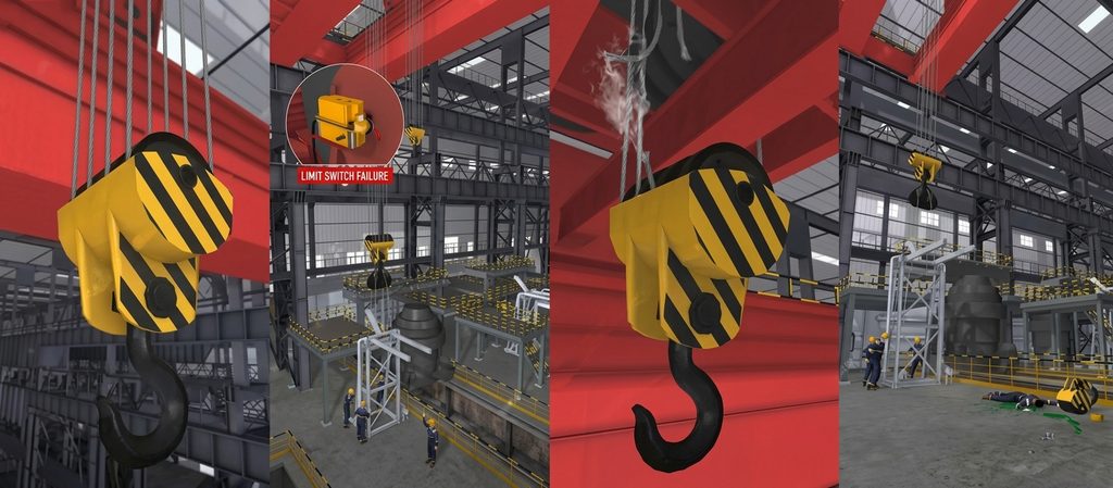
Over-hoisting is the loss of control over vertical hook travel at the upper extreme of the hoist’s range, as defined under hoist safety standards including ASME B30.16 и OSHA 1910.179.
In normal operation, the upper limit switch cuts power to the hoist motor before the hook block can reach the drum. Over-hoisting happens when that cut-off fails — for any reason — and the hook continues to travel upward unchecked. The resulting collision generates enormous shock loads: the wire rope, which has no slack to absorb impact energy, typically fails at or near the drum, and the load falls.
It is worth being precise about one common misconception: the upper limit switch is a safety device, not an operational one. Routinely driving the hook into the limit switch to “gain extra height” defeats its function. Once the switch contacts have been struck repeatedly, they wear or stick — and the next time the hook rises, there is nothing left to stop it.
Why Over-Hoisting Happens: Equipment Causes
Equipment failures account for the majority of over-hoisting incidents. The failure mechanism differs by limit switch type, so understanding each is essential before specifying replacements or setting inspection intervals.
Rotary (Screw-Type) Limit Switch Failure
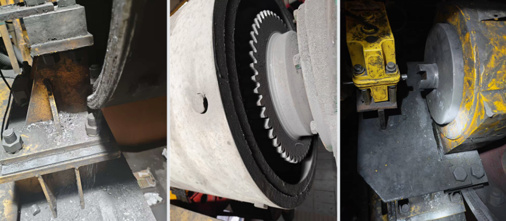
The rotary screw limiter is the most common type on overhead and gantry cranes. The drum shaft drives a screw via a coupling; a slider travels along the screw and trips a switch at the preset position.
This type fails in three distinct ways:
First, misalignment at installation. If the drum shaft centerline and the screw centerline are not co-axial, the rigid joint between them develops bending and shear stress with every rotation. Over months of operation the screw head fatigues and snaps — at which point the switch receives no signal regardless of hook position.
Second, failure to re-zero after a wire rope change. The slider’s preset position is calibrated to a specific number of drum wraps. When the rope is replaced, the wrap count resets but the slider position does not unless it is manually readjusted. On the next lift cycle the slider may reach the switch too early (nuisance trip) or, if adjusted in the wrong direction, too late — allowing the hook to over-travel before the switch fires.
Third, slider wear. In high-duty-cycle applications the slider contact surface wears down progressively, reducing the precision of actuation. At some point the slider no longer has enough travel to reliably trip the switch at the preset position.
Weight (Hammer-Type) Limit Switch Failure
The hammer-type limiter is simpler: a hanging weight sits below the hook block’s path. When the block rises to the limit, it lifts the weight, which actuates a switch above it.
Its weakness is physics, and it has two distinct failure paths.
The first is vibration and load swing. Crane operation generates continuous vibration, and off-centre loads introduce lateral sway. If the weight is mid-oscillation when the hook block arrives at the limit position, it may not be lifted squarely — the switch lever is not actuated, and the hook continues upward unchecked.
The second is drum axial float. The hoist drum is designed to sit in a fixed lateral position on its shaft, but wear in the shaft bearings or improper assembly allows the drum to shift sideways during operation. As the drum drifts, the rope exit angle changes and the point at which the rope geometry would normally lift the weight shifts with it. In a significant float condition, the hook block can pass the original trigger point entirely without contacting the weight — the limiter is physically bypassed without having failed electrically. This is why drum axial movement should be checked as a separate item during maintenance, not treated as a sub-symptom of vibration.
Contact Sticking in Any Limit Switch
Regardless of switch type, contacts can weld themselves together under electrical load — especially on cranes that see heavy start-stop cycling. Stuck contacts look fine during a visual inspection and will pass a continuity test, but they cannot open the circuit when needed. The only reliable check is a functional test under no-load conditions at the start of every shift.
Limit Switch Comparison
| Тип | Принцип работы | Key Failure Mode | Лучшее приложение |
|---|---|---|---|
| Rotary / screw | Drum shaft → screw → slider → switch | Shaft misalignment; wear; not re-zeroed after rope change | Standard overhead / gantry cranes with defined duty cycles |
| Weight / hammer | Hook block lifts hanging weight → switch | Vibration-induced weight swing; drum axial float | Simpler hoists; lower-duty-cycle applications |
| Rotary cam (geared) | Drum-linked cam shaft actuates multiple switches | Cam gear wear; requires periodic cam position verification | High-accuracy or high-cycle applications; recommended as secondary device |
Zero-Position Protection Absence
Zero-position protection prevents the hoist motor from starting if the controller handle is not at neutral when power is restored. Without it, a power interruption followed by restoration — a common event during shift changeovers or circuit maintenance — can cause the motor to run at whatever speed the handle was last set to, bypassing normal start sequencing and any limit switch that depends on a controlled start.
A missing or failed zero-position relay does not cause over-hoisting directly, but it removes one of the circuit-level backstops that would otherwise catch a compromised limit switch.
Why Over-Hoisting Happens: Human and Management Causes
Equipment factors set the conditions; human factors often provide the trigger.
Using the Limit Switch as a Travel Stop
This is the single most preventable cause. Operators who routinely drive the hook to the upper limit — to maximise hook height or simply out of habit — accelerate contact wear and can cause contacts to stick. The limit switch was designed to activate occasionally, not to serve as the end-stop for every cycle.
The engineering answer is a dual-switch arrangement: a primary operational limit switch (set slightly below maximum travel) that the operator should never intentionally reach, wired in series with a secondary emergency limit switch at the true mechanical limit. The secondary switch is wired fail-safe — if it trips, the hoist locks out until maintenance inspects both switches. This setup means the first switch failure is detected before the second is needed.
Side-Pull and Oblique Lifting
Rigging a load off-centre creates lateral rope force as the hook rises. That lateral force can knock the weight assembly of a hammer-type limiter out of alignment, damage the rope guide, or accelerate drum-edge wear — all of which increase the probability that the limit switch will not function correctly when needed.
Distraction and Misoperation
Standard operating errors include: pulling the wrong lever direction (confusing raise and lower), leaving the controller handle off neutral before power restoration, or losing situational awareness during multi-crane operations. These are management and training issues, not equipment ones — but they become fatal when a limit switch is already degraded.
How to Fix an Over-Hoisting Event
When an over-hoisting incident occurs, the crane must be taken out of service immediately. A structured return-to-service procedure prevents the same failure from repeating.
- Isolate and lock out the crane before any inspection.
- Inspect the wire rope along its full length, paying particular attention to the drum wrapping zone and any point where impact forces may have deformed the rope. Any crushed, kinked, or birdcaged section is cause for immediate replacement — even if the rope appears intact, internal wire fractures may not be visible.
- Identify the failed limit switch type and failure mode using the table above. Replace the switch; do not attempt to repair stuck contacts by sanding or bending.
- Re-check all mechanical alignments: drum shaft-to-screw concentricity for rotary types; weight suspension geometry for hammer types.
- Recalibrate the switch position with no load attached, testing actuation at the correct hook height before full-load operations resume.
- Test zero-position protection by intentionally leaving the controller handle in a working position, cutting and restoring power, and verifying the motor does not start.
- Review operator logs for the period leading up to the incident. Repeated limit-switch contacts showing in logs, or operator reports of “rough stops,” are advance warning signs that should trigger preventive replacement rather than waiting for a failure.
How to Prevent Crane Over-Hoisting
Prevention works at three levels: hardware, inspection, and behaviour. All three are needed; any single layer can fail.
Technical Safeguards
Install dual limit switches as described above — one operational, one emergency, wired in series with fail-safe logic. This is the most effective single hardware change available.
Anti-over-hoisting monitoring systems are available for higher-risk applications: electronic height encoders that monitor hook position in real time and cut power before the mechanical limit is reached, independent of the limit switch circuit. These are particularly valuable on cranes where vibration or high cycle rates make mechanical limit switches unreliable.
Specify the correct limit switch type for the application. Rotary cam switches offer better repeatability in high-cycle environments; hammer-type switches are acceptable for lower-duty applications but should always be paired with a secondary switch.
Daily Inspection Protocol
The functional test below should be completed before the first lift of every shift, with no load attached:
- Slowly raise the hook until the limit switch trips. Confirm the hoist motor stops and the hook cannot be raised further with the raise control held.
- Lower the hook several metres, then attempt to raise again — the hoist should respond normally.
- If the hoist does not stop at the limit, or if it stops but does not restart correctly on the lower attempt: take the crane out of service and notify maintenance before any load is attached.
Operator Training and Behavioural Controls
- Operators must understand that the upper limit switch is a last-resort safety device, not a working stop. This should be explicitly covered in initial training and periodic refreshers.
- Side-pull and oblique lifts must be prohibited by written procedure and enforced by supervisors on the floor.
- Shift handover should include a verbal confirmation of limit switch status, not just a signed log entry.
Management and Compliance Requirements
Under OSHA 1910.179, all electric traveling overhead cranes are required to have functional upper-limit devices that stop the hoisting motion before the hook block reaches the drum. Compliance requires documented functional tests — a visual inspection of the switch alone does not satisfy the standard.
Under ASME B30.2 (overhead and gantry cranes), periodic inspections must cover limit switch condition and function. Inspection frequency depends on the crane’s service classification, but functional tests at each shift are widely accepted practice for cranes in regular use.
Crane owners and facilities managers should maintain a written inspection log that records each functional test result, any switch replacement, and any recalibration following a rope change. This log is the primary evidence of compliance and the first document requested following an incident.
Заключение
Crane over-hoisting is preventable. The failure chain is almost always the same: a limit switch that was either degraded by routine misuse or failed mechanically, with no secondary device to catch the miss. The fixes are well understood — dual limit switches, daily functional tests, and operators who know why they should never intentionally strike the upper limit.
The single most cost-effective action most facilities can take today is a functional limit switch test at the start of every shift. If that test reveals a problem, the crane stops before a load is ever attached. If it doesn’t, you have documented evidence of a compliant inspection — the kind that matters when an incident investigator arrives.
For any crane returning to service after an over-hoisting event, all seven steps in the return-to-service procedure above should be completed and documented before operations resume.

Алан
Специалист по крановым решениям · Voitto Crane
Специализируемся на экспортных решениях в области мостовых кранов, козловых кранов, поворотных кранов, портовых кранов и мостовых кранов. Более 10 лет помогаем глобальным клиентам в проведении предпродажных консультаций, выборе грузоподъемности и разработке конфигураций с учетом специфики объекта.
ЧАСТО ЗАДАВАЕМЫЕ ВОПРОСЫ
Q1:What is crane over-hoisting?
Crane over-hoisting occurs when the hook block travels past the hoist’s designed upper limit and strikes the drum, trolley frame, or crane structure. It is caused by the failure — or deliberate bypass — of the upper limit switch, and can result in wire rope failure and a dropped load. It is also referred to as an over-winding or over-travel accident.
Q2:What causes an upper limit switch to fail?
The three most common causes are: contacts that have welded together from repeated electrical switching (contact sticking), mechanical wear or misalignment in rotary screw-type switches, and vibration-induced movement in hammer-type switches that prevents the weight from being lifted cleanly. Failure to re-calibrate the switch after a wire rope replacement is also a frequent cause.
Q3:How do I test a crane’s upper limit switch?
With no load attached, slowly raise the hook until the limit switch trips and the motor stops. Lower the hook a few metres, then attempt to raise again — normal operation should resume. If the motor does not stop at the limit position, remove the crane from service immediately and have the switch inspected and replaced before any load is lifted.
Q4:What is the difference between over-hoisting and two-blocking?
Over-hoisting is the general term used for overhead and gantry cranes, where the hook block rises into the drum or trolley frame. Two-blocking refers to the same phenomenon on mobile and jib cranes, where the hook block contacts the lower sheave assembly on the boom tip. Both result from upper-limit device failure; the mechanical consequences are the same.
Q5:What does OSHA require for crane upper limit switches?
OSHA 1910.179 requires all electric traveling overhead cranes to have functioning upper-limit devices that cut off hoisting motion before the hook block reaches the drum. Compliance requires documented functional tests — a visual inspection of the switch alone does not satisfy the requirement. ASME B30.2 specifies additional periodic inspection requirements depending on the crane’s service classification.




 English
  Español
  Português
  العربية
  Français
  Русский