The crane travelling static resistance calculator estimates the force required to overcome friction and track slope for normal travel. Using rated load and crane dead weight, it checks whether motors and drives can move the crane and trolley. Results support selection of matching motors, gearboxes, and wheels, and help assess wheel slip risk on sloped tracks to prevent bearing damage, rail biting, and installation-related faults.
Calculation basis: EN 13135:2026
Scope: Steel wheels with roller bearings on steel rails
Note: ISO 8686-1:2012 is not used for this equation.
Crane Travelling Static Resistance Formula
Crane Travelling Static Resistance Calculator
Calculate crane and trolley travel static resistance from rated load, self mass, wheel rolling factor and uphill gradient
Load & Site Parameters
Crane & Trolley Parameters
The calculation separates resistance into two components, then sums them:
\[F_f = (G_n + G) \times g \times f_r\] \[F_s = (G_n + G) \times g \times i\] \[F_{st,max} = F_f + F_s\]For the trolley, replace crane self mass G with trolley self mass G₁.
Parameter Definitions
| Symbol | Description | Unit |
|---|---|---|
| Gn | Crane rated load | kg |
| G | Crane self mass | kg |
| G₁ | Trolley self mass | kg |
| g | Gravity (taken as 10) | N/kg |
| fr | Rolling friction factor | — |
| i | Track gradient (uphill) | ‰ |
| Ff | Frictional resistance | N |
| Fs | Gradient resistance | N |
| Fst,max | Crane travelling static resistance | N |
Rolling Friction Factor (fr) Reference Table
The fr value depends on wheel diameter and whether the wheel is flanged or flangeless. Select the value matching your crane's travel mechanism.
| Wheel Diameter Dw | Flanged Wheels fr | Flangeless Wheels fr |
|---|---|---|
| 50 mm | 0.040 | 0.028 |
| 80 mm | 0.032 | 0.022 |
| 100 mm | 0.028 | 0.020 |
| 125 mm | 0.025 | 0.018 |
| 160 mm | 0.022 | 0.016 |
| 250 mm | 0.018 | 0.013 |
| 320 mm | 0.016 | 0.012 |
| 400 mm | 0.014 | 0.010 |
| ≥630 mm | 0.012 | 0.009 |
Notes on the Calculation
- The fr coefficient covers wheel rolling resistance, wheel bearing friction, and the additional forces from wheel flange contact — all combined into a single factor.
- Crane travel wheels are typically larger in diameter than trolley travel wheels. This calculator therefore allows separate wheel diameter selection for the crane bridge mechanism and the trolley mechanism.
- For travelling mechanisms and electric motors, power requirements are sensitive to gradient. Even a slope of 1‰ generates meaningful running resistance. When no measured gradient data is available from the facility, include an assumed gradient in the calculation to prevent selecting an undersized motor.
Applicable Crane Types
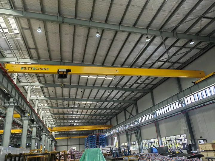
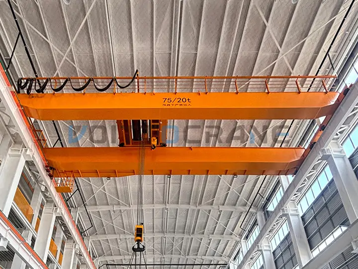
This calculation applies primarily to cranes operating in enclosed indoor factory environments:
- Single-girder overhead crane
- Double-girder overhead crane
- Single-girder gantry crane (indoor)
- Double-girder gantry crane (indoor)
- Trolley of overhead crane
- Trolley of gantry crane
What Is Crane Travelling Static Resistance?
Crane travelling static resistance is the total horizontal force a crane's travel drive must produce to initiate and sustain movement along the rail. It combines frictional resistance — from rolling contact between steel wheels and steel rail — and gradient resistance from any slope in the track, however small.
Knowing this value is a required step in motor selection. If the motor's rated torque at the wheel does not exceed Fst,max multiplied by the wheel radius, the crane will stall or overload at startup. Conversely, overestimating resistance leads to unnecessarily large and costly drive systems.
Why the Gradient Matters Even Indoors
Indoor crane rails are rarely perfectly level. Foundation settlement, thermal movement, and installation tolerances all create effective slopes along the travel path. EN 13135:2026 requires designers to include an assumed gradient when measured site data is unavailable. A value of 1‰ to 1.5‰ is typical for standard factory floors; use up to 3‰ for older or less controlled foundations.
Gradient resistance Fs matters for a second reason beyond motor sizing: if Fs exceeds available braking force, the crane will slide on the slope after the drive stops. This causes uncontrolled movement, bearing overload, and eventual rail biting. Verifying that braking capacity exceeds Fs is therefore a safety check, not just an engineering refinement.
Understanding the Friction Factor fr
The fr value is not a simple rolling resistance coefficient. In crane engineering it combines three effects:
- Rolling resistance between wheel tread and rail head — proportional to load, inversely proportional to wheel radius.
- Bearing friction in the wheel axle bearings — also reduced by larger wheel diameter, since a larger diameter increases the mechanical advantage at the bearing.
- Flange friction and skewing forces — only present in flanged wheels, from lateral contact between the flange and the rail head during travel and curve negotiation.
This explains why flanged wheels always have a higher fr than flangeless wheels of the same diameter, and why larger wheel diameters consistently yield lower fr values.
Crane Travel vs. Trolley Travel: Why Separate Calculations
The crane bridge travel mechanism and the trolley travel mechanism carry different total masses and use different wheel diameters, so their resistance values must be calculated separately.
The crane bridge mechanism supports the full rated load plus the entire crane structure: bridge girders, end carriages, cross-members, and electrical equipment. The trolley mechanism supports only the rated load plus the trolley frame, hoist, and hook assembly — a much smaller dead weight. Trolley wheels are almost always smaller in diameter, resulting in a higher fr and therefore a proportionally higher resistance per unit load.
Using a single combined calculation for both mechanisms would either oversize the trolley drive or undersize the bridge drive. The separation also matters for wheel selection: trolley wheels operating at higher fr values wear faster and require more frequent inspection.
FAQ
Q1:What gradient value should I use if I have no site measurements?
EN 13135:2026 recommends including an assumed gradient to account for installation tolerances and long-term foundation settlement. For standard indoor factory floors, 1‰ to 1.5‰ is a common assumption. For older buildings or less controlled foundations, use up to 3‰. When measured data is available from a laser level survey of the rails, use the measured worst-case gradient.
Q2:Does this calculation include dynamic or inertia forces?
No. This is a static resistance calculation — it gives the steady-state force to maintain travel, not the peak force during acceleration or emergency braking. Full motor selection also requires dynamic force analysis using the crane's target acceleration time, travel speed, and drive control type (DOL, soft-start, or VFD).
Q3:Can I use this for outdoor gantry cranes?
The EN 13135:2026 formula used here covers steel wheels on steel rails under normal indoor conditions. Outdoor cranes require additional resistance components: wind load, skewing forces from lateral wind, and in some regions, snow and ice loading on the rail. Use this calculator for the base friction and gradient resistance, then add those environmental loads separately following your applicable design standard.
Q4:Why is the fr value higher for smaller wheels?
Both rolling resistance and bearing friction scale inversely with wheel radius. A smaller wheel creates higher contact pressure at the tread, increasing deformation energy loss at each revolution. It also provides less mechanical advantage at the bearing journal, so bearing drag contributes more to total resistance per unit of load. Larger wheels are always more efficient; their higher cost and weight are justified on long-travel, heavily loaded cranes.
Q5:What does wheel slip risk mean, and how does the calculator help?
Wheel slip occurs when the horizontal force demand on the wheels — primarily gradient resistance Fs on a stopped crane — exceeds the available friction between the wheel tread and rail. The maximum static friction force is approximately the wheel load multiplied by the wheel-rail adhesion coefficient (typically 0.12 to 0.20 for dry steel on steel). If Fs approaches or exceeds this limit, the crane will slide on the slope after stopping. The calculator makes the Fs value explicit so it can be compared directly against braking and adhesion capacity.
Q6:Is this the same as the ISO 8686-1 travelling resistance formula?
No. ISO 8686-1:2012 is a general load combination standard for crane structure design and uses different resistance coefficient definitions. EN 13135:2026 provides the specific travelling mechanism resistance formula and fr table used here. The two standards are complementary but not interchangeable for this calculation. Always confirm which standard your project specification requires.

 English
 Español
 Português
 العربية
 Français
 Русский