
Crane wheel flange wear — the progressive damage caused by sustained contact between the wheel flange and the side of the running rail — does not resolve itself and cannot be managed by lubrication alone. Once the underlying cause is identified, corrective work must be sequenced correctly: applying adjustments in the wrong order wastes time, produces misleading results, and in some cases redistributes the contact force without eliminating it.
The problem is known by several names depending on where you operate. North American engineers typically call it rail biting ou crane skewing. European maintenance teams use flange rubbing. In Chinese and much of Asian crane industry practice, the direct term rail gnawing (啃轨) is common. UK and Indian engineers working with European-origin cranes often refer to the trolley mechanism as the crab and describe the same phenomenon as crab flange wear. Whatever the terminology, the corrective approach is the same.
This article covers five field-correctable solutions — with step-level procedures where the work involves physical adjustment — and five engineering improvements for cases where standard corrections are insufficient or where gnawing recurs after repeated adjustment. It assumes you have already identified the cause category using the diagnostic framework in the companion article: Crane Wheel Flange Wear: 5 Warning Signs and 6 Root Causes.
Obter cotação- 1 Before You Start: Replacement Thresholds and Scrap Criteria
- 2 Solution 1: Correct Wheel Tread Dimensions
- 3 Solution 2: Adjust Wheel Alignment by Shimming
- 4 Solution 3: Survey and Correct Rail Installation Accuracy
- 5 Solution 4: Synchronize the Drive System
- 6 Solution 5: Operator Training and Inspection Discipline
-
7
5 Engineering Improvements for Chronic and Complex Cases
- 7.1 Improvement 1: High-Flange, Large-Radius Transition Wheels
- 7.2 Improvement 2: Tapered Tread Retrofit on Drive Wheels
- 7.3 Improvement 3: Increase Bridge Horizontal Rigidity
- 7.4 Improvement 4: Flangeless Wheels with Horizontal Guide Rollers
- 7.5 Improvement 5: Hydraulic Fluid Coupling or VFD Drive Upgrade
- 8 Priority Correction Sequence
- 9 Conclusão
Before You Start: Replacement Thresholds and Scrap Criteria
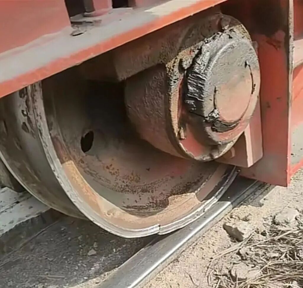
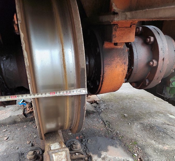
Corrective adjustment is only appropriate when the wheels and rail are still within recoverable condition. If wear has exceeded the thresholds below, replacement must precede any alignment work — adjusting worn-out components to correct geometry achieves nothing if the contact surfaces are already beyond serviceable condition.
Wheel Scrap Thresholds
Per GB/T 10183.1-2018 and general industry practice for overhead crane and gantry crane wheels:
- Flange wear: When flange thickness has worn to less than 60% of the original design dimension (i.e., wear exceeds 40% of design flange thickness), the wheel must be scrapped and replaced. Continuing to operate beyond this threshold risks flange fracture and derailment.
- Tread wear: When tread thickness has reduced by more than 15% of the original dimension, the wheel must be replaced. A worn tread reduces the effective wheel diameter, which introduces the speed differential between paired drive wheels that is one of the primary causes of rail gnawing.
- Drive wheel diameter tolerance: The diameter difference between two drive wheels sharing the same runway rail must not exceed 0.2% of the nominal diameter. For a 500 mm drive wheel, this means a maximum permissible difference of 1.0 mm. Beyond this, the resulting speed differential is sufficient to generate progressive lateral drift. For driven (idle) wheels the tolerance is slightly more permissive at 0.2% of nominal diameter; for electric hoist wheels, up to 1% is generally accepted.
- Tread ovality: A wheel tread that is no longer circular — typically caused by flat spots from wheel locking during braking — must be replaced when ovality exceeds 1 mm.
- Cracks: Any visible crack in the wheel, regardless of location, requires immediate scrapping. Do not attempt to weld-repair cracked crane wheels in field conditions.
Rail Joint and Surface Condition
Before beginning alignment work, check the following rail conditions and correct them first:
- Rail joint vertical step: must not exceed 1 mm
- Rail joint horizontal offset: must not exceed 1 mm
- Rail joint gap: must not exceed 2 mm (in regions with seasonal temperature variation exceeding 20°C, or during winter installation, allow up to 4–6 mm)
- Rail surface contamination (oil, water, frost): clean to bare metal before any diagnosis or adjustment
Solution 1: Correct Wheel Tread Dimensions
Dimensional verification of all drive wheel treads is the mandatory first step — not an optional preliminary. The most common error in rail gnawing correction work is proceeding directly to alignment shimming without confirming that paired drive wheels are still within diameter tolerance. Shimming a wheel pair with a 2 mm diameter difference into perfect angular alignment achieves nothing: the speed differential is still there, and the gnawing will return.
Measure and Equalize Drive Wheel Diameters
Using a micrometer or a dial gauge setup referenced to the wheel axle center, measure the tread diameter of every drive wheel. Record measurements for each wheel individually. Compare paired drive wheels — those sharing the same runway rail on the same end of the bridge travel mechanism (end truck in North American terminology, end carriage in European practice) or the trolley (crab).
If the diameter difference between a paired set exceeds 0.2% of nominal diameter, the corrective action depends on the magnitude of wear:
- Minor difference, both wheels within serviceable tread thickness: Machine both wheels on a lathe to equalize the diameters at the lower value, then verify that the resulting tread thickness still exceeds the 85% minimum. Follow with surface hardening treatment (quenching and tempering) to restore wear resistance.
- One wheel significantly more worn than its pair: Replace both wheels simultaneously as a matched pair. A new wheel installed alongside a worn wheel creates a diameter differential equal to the worn wheel’s tread loss — which immediately recreates the speed imbalance that was causing the gnawing.
Verify Tapered Tread Orientation
If the drive wheels use a tapered (conical) tread — a 1:10 cone angle is the standard configuration on Chinese-specification cranes following GB/T design rules — confirm the installation orientation before any other adjustment is made. The correct assembly is: large end of the cone facing inward toward the bridge centerline; small end facing outward.
This orientation enables the self-centering mechanism that tapered treads are designed to provide: when the bridge drifts laterally, the leading wheel contacts at a larger effective diameter, generating a corrective speed differential. Reversed orientation eliminates this effect and actively worsens gnawing.
If wheels are found reversed — a common error after replacement when the original drawing was not consulted — they must be dismounted and reinstalled correctly. No shimming or alignment correction will compensate for wrong taper direction.
Solution 2: Adjust Wheel Alignment by Shimming
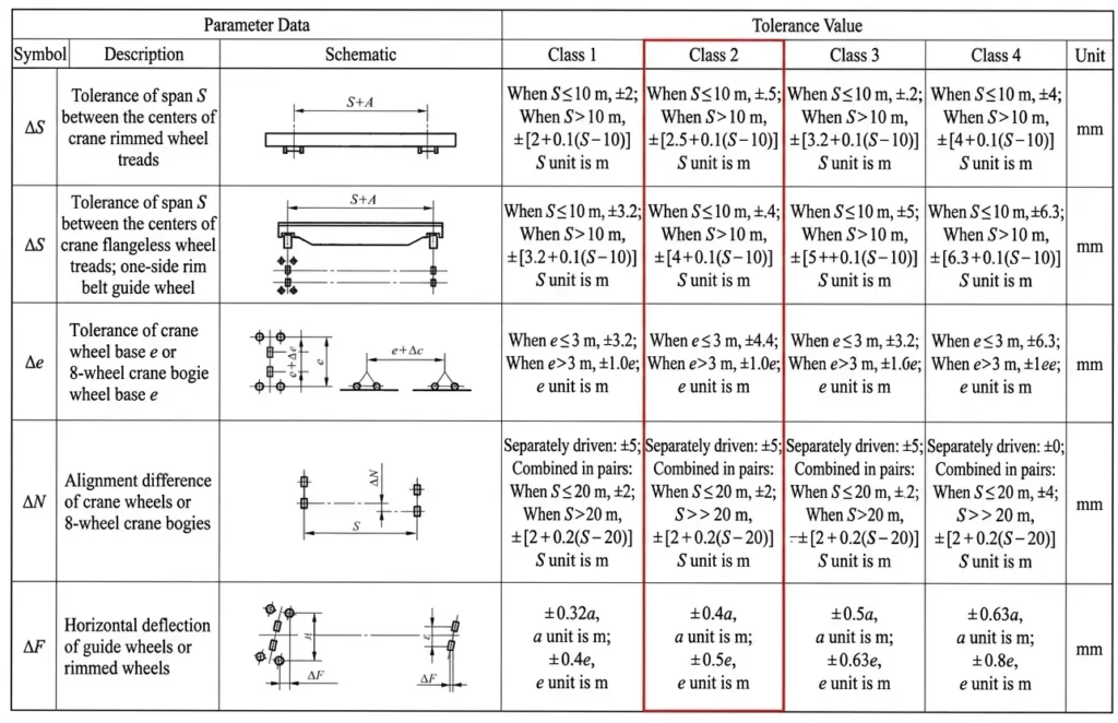
Once wheel dimensions are confirmed correct or replacement wheels have been installed, wheel alignment is the next correction to make. For angle-box (角型箱) wheel groups — the standard configuration on Chinese GB/T overhead cranes and gantry cranes — the shimming procedure below applies. For other wheel group configurations (e.g., European-standard bogie assemblies), follow the manufacturer’s alignment specification for the specific type.
The alignment tolerances that define the target condition are (per GB/T 10183.1-2018, tolerance class 2 for standard applications):
- Horizontal wheel deviation: ≤ L/1000
- Vertical wheel deviation: ≤ L/400 (where L is the reference measurement length at the wheel)
- Four-wheel diagonal difference: ≤ 5 mm
Tolerance class 1 applies for precision applications (high-speed cranes, clean-room overhead cranes, precision manufacturing environments) and specifies tighter limits — consult the standard for the specific values.
Correcting Horizontal Wheel Deviation
Horizontal deviation is the in-plan angle between the wheel centerline and the rail centerline — the wheel is yawed left or right relative to the travel direction.
Measurement: Stretch a 0.5 mm steel reference wire close to the front and rear faces of the wheels on one side of the bridge, anchored at the end stops. Measure the perpendicular distance from the wire to the wheel face at the front and rear of each wheel. The difference between these two measurements is the horizontal deviation for that wheel. Identify the wheel with the largest deviation.
Shimming procedure:
- Position a hydraulic jack under the end truck frame at the location of the wheel to be adjusted. Jack up until the wheel clears the rail running surface.
- Loosen the angle-box mounting bolts to approximately 70% of specified torque — enough to allow lateral movement without full release.
- If the wheel is deviated outward (yawed toward the outer rail): insert shim stock between the inner face of the angle box and the vertical key plate.
- If the wheel is deviated inward (yawed toward the bridge centerline): insert shim between the outer face of the angle box and the vertical key plate.
- Standard shim increment: 1–2 mm per adjustment step. For severe gnawing that has been developing for an extended period, use the smaller increment and iterate — attempting to correct a large deviation in one step often overshoots.
- Lower the jack and allow the wheel to seat on the rail under its structural load.
- Tighten angle-box bolts to full specified torque.
- Conduct a short test traverse (10–20 meters) and re-measure deviation. If deviation remains outside tolerance, repeat steps 1–7 with the same shim direction. If the adjustment has overshot, reduce shim thickness. Expect two to three iterations to reach tolerance.
Correcting Vertical Wheel Deviation
Vertical deviation is the out-of-plumb angle of the wheel relative to the rail top surface — the wheel is tilted inward or outward at the top.
The measurement and shimming approach mirrors the horizontal procedure, with one difference: the shim is inserted between the angle-box face and the horizontal key plate (rather than the vertical plate used for horizontal deviation correction).
- Wheel tilted inward at the top: shim between the outer face of the angle box and the horizontal key plate.
- Wheel tilted outward at the top: shim between the inner face and the horizontal key plate.
Critical follow-up step: After completing vertical deviation correction, re-check horizontal deviation before closing up the work. Vertical shimming can introduce a horizontal angular component as a side effect. Both deviations must be within tolerance simultaneously before the adjustment is considered complete.
Solution 3: Survey and Correct Rail Installation Accuracy
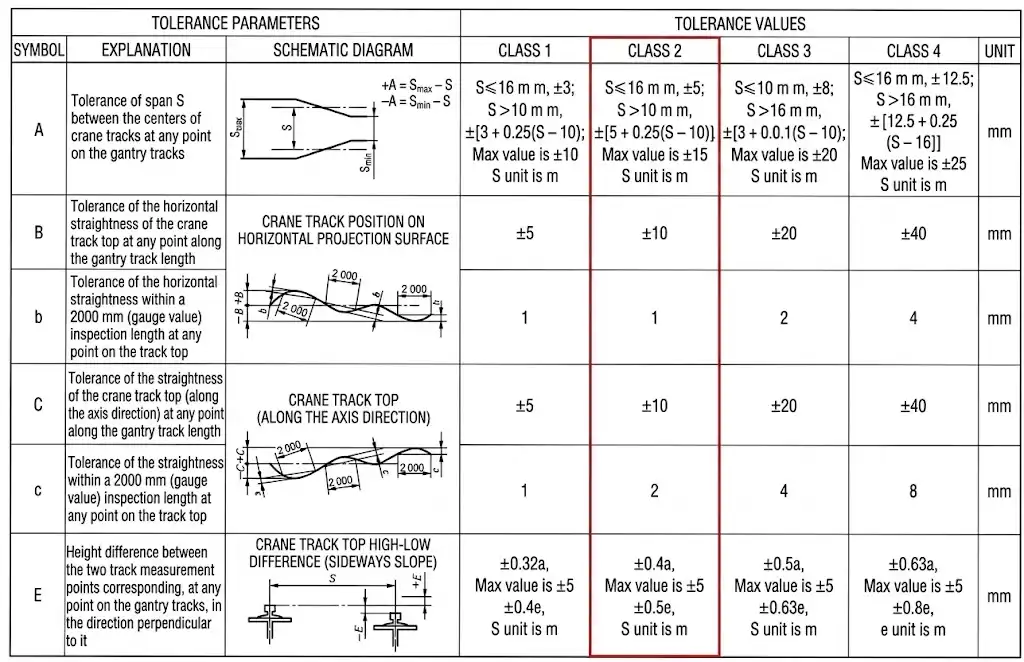
Rail-origin flange wear is characterized by its location-specificity: gnawing that occurs at repeatable positions along the runway, disappears between those points, and often produces an impact sound as the crane passes through the affected section. This pattern distinguishes rail problems from wheel and drive problems, which tend to produce continuous gnawing.
Full-Length Rail Survey
Conduct an elevation survey of both runway rails at 2-meter intervals along the full working length. Record absolute elevation at each station and calculate the cross-rail elevation difference at every survey point. Per GB/T 10183.1-2018, the relative elevation difference between the two runway rails at any cross-section must be within the tolerance for the crane’s class and span.
Simultaneously check rail straightness in plan view: stretch a reference wire between end stops and measure horizontal offset at each 2-meter station. Plot the offset values to identify sections with horizontal kinks or curves that exceed the straightness tolerance.
At every rail joint, measure:
- Vertical step between adjacent rail ends (target: ≤ 1 mm)
- Horizontal offset between adjacent rail ends (target: ≤ 1 mm)
- Joint gap (target: ≤ 2 mm, or up to 6 mm for cold-climate winter installations)
Check that all rail fastening clips and bolts are tight. Rail fastenings that have loosened under repeated dynamic loading allow the rail to move laterally under crane travel, creating a running geometry that differs from the static survey reading — a source of gnawing that no amount of alignment adjustment will correct until the fastenings are re-secured.
Rail Corrections
Elevation correction: Achieved by shimming under the rail or adjusting rail pad thicknesses. For larger elevation errors associated with foundation settlement (common on outdoor gantry crane runways), re-grouting or repositioning of the runway beam support may be required.
Horizontal straightness correction: Loosen rail fastenings over the affected section, reposition the rail laterally using the survey measurements as the target, and re-fasten. Recheck straightness after re-fastening — the clamping force can introduce minor position shifts.
Rail joint correction: Grind or machine the joint faces to eliminate vertical steps. For joints with excessive gap, insert joint fishplates and re-weld where rail type permits. For temporary field correction, smooth the joint transition with a grinding wheel to eliminate the abrupt step that produces the impact sound and lateral excursion.
Surface contamination: Clean the full rail length with a degreaser before any other diagnostic step. Oil or water contamination causes wheel slip that mimics drive imbalance or diameter mismatch in its symptom pattern. Run the crane after cleaning and confirm whether gnawing persists before proceeding to mechanical investigation.
Solution 4: Synchronize the Drive System
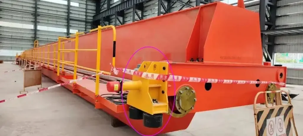
Drive system corrections address rail gnawing that is most pronounced during acceleration from standstill and during braking — the characteristic signature of brake torque or mechanical drive imbalance. If gnawing is present throughout travel at constant speed, drive system correction alone will be insufficient; verify wheel dimensions and rail geometry first.
Brake Torque Equalization
Measure the braking torque of each drive brake independently using a torque wrench at the drum or disc. The two values must be equal or within a close tolerance. Adjustment method depends on brake type:
- Spring-applied, electrically released brakes (most common on overhead cranes): Adjust spring compression. If one side is over-torqued, reduce its spring compression to match the lower side. Do not increase the lower side to match the higher — over-braked systems generate excessive stopping forces that stress the bridge structure.
- For asymmetric load applications (where one end of the bridge consistently carries more load): a modest brake torque increase on the heavier end is acceptable, but should be documented and should not exceed the manufacturer’s adjustment range.
Gear Backlash and Shaft Key Check
With the drive mechanisms de-energized and the crane secured against movement, remove access covers and measure gear mesh backlash on both drive sides using a dial indicator. Backlash values significantly different between the two sides indicate uneven gear tooth wear. If backlash on one side exceeds twice the value of the other, gear replacement on that side is required.
Check shaft keys by attempting to detect rotational play between the shaft and gear hub by hand. Any detectable movement — which should be zero in a correctly keyed joint — indicates a worn or undersized key that must be replaced before any other drive adjustment is made. A loose shaft key intermittently disconnects the drive on that side, producing the characteristic start-up skew symptom.
Motor Speed Verification and Electrical Checks
For separately driven bridge mechanisms — where each end truck has its own motor — verify that both motors produce the same no-load shaft speed under identical electrical supply conditions. A speed difference exceeding approximately 1–2% is sufficient to generate persistent lateral drift on a medium-to-long span bridge.
Para wound-rotor motors with resistance speed control (common on older Chinese-standard cranes): verify that rotor resistance steps are equal on both sides; check for loose or corroded connections in the rotor circuit; confirm that no rotor circuit phases are open. An open phase on one rotor circuit causes that motor to run at reduced torque and speed, producing a continuous lateral force.
Para VFD-controlled systems: confirm that both drives receive identical speed reference signals; verify that any speed feedback encoders are functioning correctly and that their signals match the commanded reference. A failed or slipping encoder on one side will cause that drive to run open-loop, eliminating the speed synchronization that VFD control is intended to provide.
If motor speed differences cannot be corrected by electrical adjustment, replace motors in matched pairs from the same manufacturer batch. Nominally identical motors from different production batches can differ in speed characteristic by enough to cause persistent gnawing on long-span bridges.
Solution 5: Operator Training and Inspection Discipline
Operational factors are both a primary cause of some gnawing cases and an accelerator of mechanically-originated cases. This solution does not substitute for mechanical correction but is required alongside it — corrected gnawing recurs quickly in cranes that continue to be operated beyond rated load or subjected to collision events.
Enforce Rated Load Limits
Chronic overloading distorts end truck frames and changes wheel geometry progressively. Even moderate overloading — operating at 110–120% of rated capacity — accelerates bearing wear and introduces plastic deformation in end truck structural members. Any crane that has experienced sustained overloading should have its end truck geometry (wheel gauge, diagonal, verticality) resurveyed before relying on the previous alignment record.
Anti-Collision Maintenance
Bridge-to-bridge collisions on shared runways generate lateral impact loads far in excess of design values. Maintain physical buffer systems, proximity sensors, and travel limit switches in working order. End trucks that have been involved in a collision event must be dimensionally checked before returning to service — the deformation may not be visible but will produce gnawing that appears soon after the crane resumes operation.
Integrate Rail Gnawing into Pre-Shift Inspection
Train operators to include a visual check for gnawing indicators in the pre-shift walkthrough: inspect the rail side for new polished marks, check the inner face of wheel flanges for burring, and listen for the characteristic hissing sound during the first traversal of the runway. Early identification — within the first week of onset — allows correction with shimming adjustments. Gnawing allowed to run for months typically requires rail replacement and may require structural repair.
5 Engineering Improvements for Chronic and Complex Cases
When standard field corrections have been applied correctly but gnawing recurs within weeks, or when the geometry source of the gnawing cannot be corrected without major structural dismantling, the following engineering modifications provide more durable solutions.
Improvement 1: High-Flange, Large-Radius Transition Wheels
A wheel with a taller flange — approximately double the standard height — and a significantly larger transition radius between flange and tread delivers two compounding benefits that standard-geometry wheels cannot provide.
The increased flange height spreads any residual lateral contact force over a larger contact area, reducing contact pressure and extending the time between damage threshold wear levels. More importantly, the large-radius tread-flange transition changes the nature of the contact when the wheel runs off-center: instead of the flange side contacting the rail web (the high-stress condition that causes rapid wear), the curved transition zone contacts the rail top edge. The contact force at this point has a horizontal component directed back toward the rail centerline — a passive self-correcting force. On drive wheels, this effect is amplified because the larger contact diameter at the offset position generates a higher linear velocity, pulling the lagging side forward and correcting the skew dynamically.
In documented cases, replacing standard drive wheels with high-flange large-radius wheels has extended wheel service life by more than double on cranes with chronic gnawing that could not be fully eliminated by alignment adjustment alone. This is the most cost-effective first engineering modification for cranes with persistent geometry-origin gnawing.
Improvement 2: Tapered Tread Retrofit on Drive Wheels
For cranes originally equipped with cylindrical tread drive wheels, converting the drive wheels to a 1:10 tapered tread (large end inward) introduces the self-centering mechanism. When the bridge drifts laterally, the leading drive wheel contacts at a larger diameter, running faster than the lagging side and generating a corrective differential that pulls the bridge back into alignment.
This modification requires machining or replacing the drive wheels and confirming that the new taper geometry is compatible with the running rail profile in use. Correct orientation is critical: wrong taper direction will worsen gnawing, not improve it. A trial installation on one end truck, with performance monitoring before converting the remaining wheels, is the recommended approach when this modification has not been applied to this crane type before.
Improvement 3: Increase Bridge Horizontal Rigidity
When gnawing is partly driven by dynamic bridge skewing under load — the bridge twisting in plan as the trolley moves or as loads are applied asymmetrically — increasing the horizontal rigidity of the bridge structure reduces the dynamic skew amplitude. This is typically achieved by adding horizontal bracing between the main girders at the trolley rail level or by reinforcing the connection stiffness between the main girders and the end trucks.
Structural reinforcement requires an engineering assessment of the existing bridge design. Stiffness modifications change the load path through the structure and must not compromise the primary load-carrying members. Do not add horizontal bracing without confirming that the existing connections and members can carry the modified load distribution.
Improvement 4: Flangeless Wheels with Horizontal Guide Rollers
Replacing flanged wheels with flangeless wheels and installing horizontal guide rollers — running against the rail side or a dedicated guide rail — completely decouples the lateral guidance function from the tread-rail interface. In this configuration, the tread carries only vertical load; lateral guidance is handled by guide rollers that are sized and positioned specifically for that purpose.
This is the most complete engineering solution for eliminating flange wear: with no flange making contact during normal operation, the wear mechanism is removed entirely. The configuration is standard on automated cranes (automated storage/retrieval systems, automated stacking cranes) where precise lateral positioning is required continuously. On conventional cranes, the cost of conversion is typically justified only when gnawing is severe and chronic and has not responded to all other corrective measures. The guide roller configuration also provides an important secondary benefit: it prevents derailment in crane types where derailment risk is a safety concern.
Improvement 5: Hydraulic Fluid Coupling or VFD Drive Upgrade
When drive system speed imbalance is a confirmed contributing cause and cannot be eliminated by mechanical adjustment — typically due to mismatched motor characteristics or inherent speed variation under varying load — two drivetrain upgrades provide a durable solution.
Hydraulic fluid coupling: Inserting a hydraulic fluid coupling between the motor and gearbox on each drive side provides inherent slip accommodation. Small speed differentials between the two sides are absorbed by slip within the coupling rather than transmitted as lateral forces to the wheel flanges. This approach is particularly effective on long-span bridges and on cranes with frequent load variation, where the speed differential between the two sides changes dynamically as load shifts. Fluid couplings also reduce mechanical shock during start-up, addressing the braking-phase gnawing that brake torque imbalance produces.
Variable frequency drive (VFD) with closed-loop speed synchronization: VFD control of both bridge drive motors, with a common speed reference and closed-loop speed feedback from both sides via encoders, eliminates the speed differential at the electrical source. VFD systems also provide controlled ramp acceleration and deceleration, removing the sudden torque application at start-up and braking that drives gnawing in mechanically imbalanced systems. For cranes being upgraded from contactor-resistance control, VFD conversion is among the most effective single improvements available for eliminating drive-origin flange wear — with the additional benefits of reduced energy consumption and extended motor service life.
Priority Correction Sequence
When multiple causes are present — which is typical in established gnawing cases — apply corrections in this order to avoid producing results that are confounded by multiple simultaneous changes:
| Step | Action | Reason |
|---|---|---|
| 1 | Clean rail running surfaces | Contamination mimics mechanical causes; eliminate this variable first |
| 2 | Check and correct rail geometry | Rail corrections provide a stable reference datum for wheel alignment measurement |
| 3 | Verify wheel scrap thresholds | Replace worn wheels before any alignment adjustment |
| 4 | Verify tapered tread orientation | Wrong orientation cannot be compensated by shimming |
| 5 | Shim wheel alignment | With correct rail and wheels in place, alignment corrections produce reliable results |
| 6 | Synchronize drive system | With geometry confirmed correct, drive imbalance is isolated and addressable |
| 7 | Evaluate engineering improvements | Apply only after standard corrections have been fully implemented and assessed |
After each correction step, conduct a test traverse under representative load conditions and observe the gnawing pattern before proceeding to the next step. Correcting multiple variables simultaneously makes it impossible to identify which change produced the improvement — or which remaining cause is still producing residual gnawing.

Alan
Especialista em soluções para guindastes · Voitto Crane
Especializada em soluções de exportação de pontes rolantes, pórticos, gruas, pórticos portuários e pontes rolantes EOT. Mais de 10 anos a ajudar clientes globais com consultoria pré-venda, seleção de capacidade e configurações específicas do local.
Conclusão
Crane wheel flange wear — whether called rail gnawing, flange rubbing, or rail biting — is a correctable condition when the right cause is addressed in the right sequence. The five solutions above cover the full range of field-addressable causes: wheel dimensions and taper orientation, wheel alignment shimming, rail geometry, drive system synchronization, and operational discipline. The five engineering improvements address the subset of cases where standard corrections are insufficient or where a structurally more robust solution is needed to prevent recurrence.
The priority correction sequence is the most important takeaway: start with contamination, then rail geometry, then wheel condition, then alignment, then drive. Applying steps out of order produces misleading results and extends the correction timeline unnecessarily.




 English
  Español
  Português
  العربية
  Français
  Русский