
Wheel flange wear — the sustained, forceful contact between a crane wheel flange and the side of the rail — is one of the most damaging and persistent faults in overhead and gantry crane operation. Left unaddressed, it accelerates wear on both wheels and rails, increases running resistance, distorts the crane’s metal structure, and in severe cases leads to derailment and serious injury.
The problem goes by several names depending on where you are. Wheel flange wear is the most widely recognized term internationally and appears in most maintenance standards and inspection checklists. Engineers and maintenance teams also encounter it as flange rubbing in European technical documentation, rail biting in North American maintenance manuals, and rail gnawing (啃轨) in Chinese technical literature — a direct translation that has become widely understood across the global crane industry. Whatever the terminology, the underlying mechanics and the diagnostic approach are the same.
This article covers what wheel flange wear looks like in the field, how to identify it early, and — critically — how to distinguish between the six categories of root cause that drive it. The companion article, How to Fix Crane Wheel Flange Wear: 5 Solutions and 5 Engineering Improvements, covers corrective and preventive action once the cause is confirmed.
Obter cotaçãoWhat Is Crane Wheel Flange Wear and Why Does It Matter


Wheel flange wear occurs when a crane wheel — on either the bridge travel mechanism (called the end truck in North America, end carriage in Europe) or the trolley travel mechanism (called the crab in UK and Indian engineering practice) — loses its lateral clearance from the rail and begins pressing against the rail side under load.
Under normal operation, a defined gap exists between the wheel flange and the rail head. That clearance allows minor misalignment to self-correct without contact. When that gap is eliminated — by wheel deviation, rail error, structural deformation, or drive imbalance — the flange begins grinding against the rail side on every pass. This condition is also referred to as rail gnawing, flange rubbing, or rail biting, all of which describe the same mechanism.
The consequences escalate in stages. Early-stage wheel flange wear increases running resistance and accelerates deterioration on both the wheel flange and the rail side. As the condition progresses, it generates lateral forces that loosen rail fasteners, fatigue the runway beams, and distort the crane bridge structure. In severe cases the wheel climbs the rail — a derailment event that can cause catastrophic equipment damage and injury.
The root causes of wheel flange wear are frequently multiple and interacting. A small wheel diameter mismatch may be tolerable on its own, but combined with a rail elevation deviation, it produces flange wear that neither cause alone would generate. This interaction effect is why symptom-based diagnosis — reading what the wear pattern tells you before reaching for a wrench — is more reliable than sequential trial-and-error adjustment.
5 Warning Signs of Wheel Flange Wear
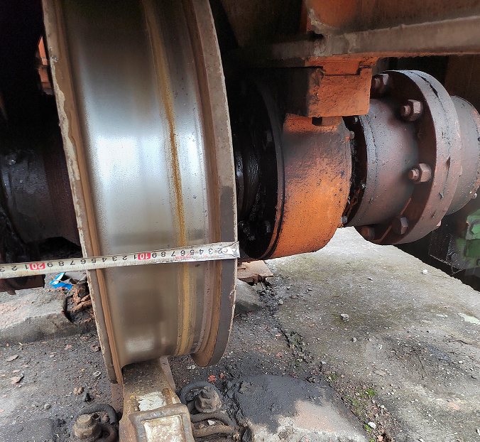
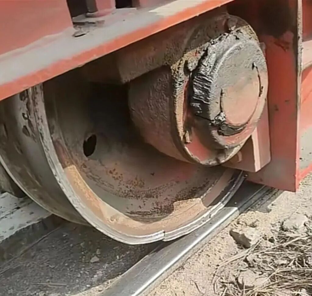
Identifying wheel flange wear early requires knowing what to look for during routine inspection. The five signs below apply to both bridge travel (end truck / end carriage) and trolley (crab) mechanisms.
Polished Marks and Burring on the Rail Side
Bright, polished contact marks on the side face of the rail are the most reliable visual indicator of wheel flange wear. In early-stage cases, these appear as a narrow shiny band on the rail web. As the condition progresses, the marks develop burrs — raised metal slivers — and in severe cases, deep longitudinal grooves are visible. The location of these marks on the rail side (inner face vs. outer face, and at what height) provides the first clue about which wheel and which direction of deviation is responsible.
Bright Spots and Burring on the Inner Wheel Flange
The inner face of the wheel flange will show corresponding wear: polished contact patches and, in advanced cases, metal burring or chipping. Under normal operation, the flange inner face should show no contact marks at all — its function is to prevent derailment, not to guide the wheel. Any visible wear on the flange inner face confirms active flange-to-rail contact and should be treated as an immediate investigation trigger, not a cosmetic issue.
Shiny Wear Marks on the Rail Top Surface
When a wheel runs with vertical tilt (vertical deviation), the tread contact area shifts toward one edge of the rail top, creating a triangular contact footprint rather than the correct full-width band. The result is a bright wear line along one edge of the rail top surface. In prolonged cases, a visible annular groove forms on the wheel tread itself. This sign is specific to vertical wheel deviation and distinguishes that cause from horizontal misalignment.
Rapid Flange-to-Rail Gap Change Over Short Travel Distance
During a slow manual inspection traverse, observe the gap between the wheel flange and the rail side at multiple points. Under normal conditions this gap is stable. In wheel flange wear conditions, the gap changes noticeably — often from near-zero contact to several millimeters of clearance — within 10 meters of travel. Rapid gap variation indicates a geometry problem: either the rail is not straight, the crane is skewing dynamically, or wheel alignment is inconsistent across the span.
Abnormal Noise and Body Skewing During Operation
Audible and motion-based signs are often the first indicators that reach the operator before any visual inspection occurs. Early-stage wheel flange wear produces a characteristic metallic hissing sound — the sustained friction of flange against rail side. As the condition worsens, this transitions to intermittent impact sounds (“clunking”) as the flange repeatedly contacts the rail. Visible body skewing — the crane bridge or trolley visibly angling during travel, especially during start-up and braking — confirms that lateral forces are acting on the structure. In extreme cases, the crane will exhibit a lurching motion or partial rail climb.
6 Root Causes of Wheel Flange Wear
The causes of wheel flange wear in bridge cranes (overhead cranes, EOT cranes) and gantry cranes fall into six categories. Most real-world cases involve two or more causes acting together — which is why the diagnostic table in the next section is essential before beginning any corrective work.
Cause 1: Wheel Machining and Installation Errors
Wheel geometry and installation accuracy are the most common source of persistent wheel flange wear, accounting for the majority of cases across both bridge and gantry crane types.
Drive wheel diameter mismatch is among the most frequently missed causes. When the two drive wheels on the same bridge end are not equal in diameter, they travel different distances per revolution. A difference as small as 1–2 mm between active drive wheel diameters can cause the bridge to accumulate lateral drift, typically becoming noticeable as flange contact after 15–20 meters of travel. The wear pattern is characteristic: it occurs consistently on the same side in both forward and return directions of travel, which distinguishes diameter mismatch from horizontal skew (where the gnawing side alternates with direction). This cause is especially pronounced in centrally-driven mechanisms where a single drivetrain serves both rails.
Horizontal wheel deviation means the wheel centerline is not parallel to the rail centerline in plan view — the wheel is canted left or right relative to the direction of travel. Per GB/T 10183.1-2018 (Cranes — Tolerances for wheels and travel and cross-travel rails), horizontal deviation should not exceed L/1000 (where L is the reference measurement length of the wheel). When this limit is exceeded, the wheel “steers” into the rail on one side during forward travel and into the opposite rail on return — the alternating-side flange wear pattern that is the key diagnostic signature of this cause. If the affected wheel is a drive wheel, the wear is more severe than on an idle wheel under the same deviation.
Vertical wheel deviation means the wheel axis is not perpendicular to the rail top surface — the wheel is tilted inward or outward. This reduces the tread contact area to a triangular footprint, concentrating load on the low edge of the tread. The result is a consistent one-sided wear pattern (the wheel always contacts the same rail face regardless of travel direction) combined with the distinctive rail-top wear mark described in the warning signs section. GB/T 10183.1-2018 specifies that vertical deviation should generally not exceed L/400 for standard tolerance class 2 installations.
Wheel gauge and diagonal deviation — when the four wheels of a bridge crane do not form a true rectangle in plan view — create a condition where the crane is geometrically forced into rail contact in at least one corner at all times. This produces simultaneous flange wear on both rail sides and is often the result of structural deformation rather than installation error alone.
Overloading and collision damage progressively worsens wheel geometry by distorting the end truck structure, causing wheel verticality, span, and diagonal tolerances to deteriorate beyond recoverable adjustment limits.
Cause 2: Rail Installation Errors
Rail installation errors cause flange wear that is typically localized — occurring at specific positions along the runway — rather than continuous. This localization is the key diagnostic clue that distinguishes rail problems from wheel or drive problems.
Rail elevation difference between the two runways is one of the most common rail-side causes. When one rail sits higher than the other, the crane leans toward the lower side during travel, generating a persistent lateral force that pushes the wheel flanges into the rail. The higher-elevation side produces outer-flange-to-rail contact; the lower-elevation side produces inner contact. When the crane suddenly tilts at a specific point and self-corrects after passing that point, excessive local elevation difference at a rail joint or a sunken support is almost certainly the cause.
Excessive rail span deviation — the distance between the two runway rails varying beyond tolerance — forces the wheel flanges into lateral contact. If the span is too wide at a given point, both flanges contact the outer rail faces simultaneously; if too narrow, both contact the inner faces.
Rail straightness deviation — horizontal kinks or curves in the rail alignment — produces flange wear that appears and disappears as the crane passes through the deviated section, often accompanied by a metallic impact sound at the transition point.
Rail top surface not vertical — a rail that is tilted laterally rather than sitting plumb — creates asymmetric tread contact identical in appearance to vertical wheel deviation. The diagnostic distinction requires checking both the rail and the wheel independently.
Contamination of the rail running surface — oil, water, frost, or machining swarf on the rail top — causes the wheel to slip and skid rather than roll cleanly, generating intermittent lateral excursions that produce flange wear. This cause is often seasonal (frost in winter, condensation in facilities with humidity variation) and is identifiable because the wear disappears after the running surface is cleaned.
Poor-quality or worn rail — rail with a non-horizontal top surface, including repurposed worn rail stock — produces chronic flange wear that is difficult to trace to any mechanical cause. Checking rail cross-section geometry is a necessary step when other causes have been ruled out.
Cause 3: Drive System Imbalance
Drive system causes produce flange wear that is most pronounced during the dynamic phases of operation — acceleration from standstill and deceleration to stop. If flange wear occurs primarily during start-up and braking and is absent during steady-speed travel, drive system imbalance is the primary suspect.
Unequal gear backlash between the two drive trains — or a loose shaft key in one drive — allows one side to lag slightly during initial acceleration. The resulting speed differential skews the bridge, initiating flange contact at the moment of peak lateral force. This type of wear is typically accompanied by visible body twist during starts.
Brake torque imbalance between the two sides creates the same lateral skew during braking. If the brake on one side is adjusted tighter than the other, that side decelerates faster, rotating the bridge in plan and pushing the leading corner’s flange into the rail. Checking and equalizing brake torque across both sides is a standard corrective step.
Mechanical obstruction in one drive train — a seized bearing, bent coupling, or partially jammed gearbox — creates a persistent speed differential. The flange wear is present throughout travel, not only at start and stop, and is accompanied by uneven motor current draw.
Electrical drive imbalances — including motor speed mismatch between the two sides, open-phase conditions on one motor’s rotor circuit, incorrectly wired resistors, or mismatched gearbox ratios — all produce lateral speed differentials that scale with load. These causes are particularly relevant in separately-driven bridge mechanisms (where each end truck has its own motor) and are now less common in VFD-controlled systems where speed synchronization is handled electronically.
Cause 4: Structural Deformation of the Bridge or Frame
Structural deformation causes flange wear that is persistent, difficult to adjust away with wheel or rail corrections alone, and often worsens progressively as the deformation grows.
Bridge girder deformation — sagging, twisting, or lateral bending of the main girder — changes the geometry of all four wheel positions simultaneously. Even if the wheels were installed correctly and the rails are in tolerance, a deformed bridge produces out-of-tolerance wheel positions at the end trucks. The diagnostic signature is that wheel alignment checks done at the end truck level show acceptable readings, but flange wear continues — because the end truck itself has moved relative to the design position.
Asymmetric loading history — a bridge that has operated for extended periods with loads consistently biased toward one end — accumulates residual lateral deformation in the bridge structure. This produces a stable, low-level flange wear pattern that does not correspond to any single rail or wheel measurement out of tolerance.
Cause 5: Tapered Tread Wheel Assembly Errors
Many crane drive wheels use a tapered (conical) tread profile rather than a cylindrical one. The taper — typically 1:10 — is intended to provide self-centering: when the bridge drifts slightly to one side, the wheel on the leading side contacts a larger tread diameter, generating a corrective speed differential that pulls the bridge back into alignment.
This self-centering effect only works if the wheels are assembled in the correct orientation: large end inward (toward the bridge centerline), small end outward. Reversing this orientation — either on one wheel or on both — eliminates the self-centering effect and actively worsens flange wear.
Both wheels reversed (small end inward): The self-centering mechanism acts in the wrong direction — amplifying lateral drift rather than correcting it. Flange wear is persistent and consistent to one side.
Both wheels oriented in the same direction (both tapers pointing the same way): Instead of the correct opposing-taper configuration, both wheels steer the bridge in the same lateral direction. The result is flange wear concentrated on the large-end flange of both wheels.
This cause is particularly relevant after wheel replacement. A maintenance team replacing worn wheels without verifying taper orientation against the original drawing can inadvertently install the replacement wheels incorrectly, creating flange wear that did not exist before the maintenance event.
Cause 6: Gantry Crane On-Site Assembly Errors
Gantry cranes (portal cranes, semi-gantry cranes, and full gantry cranes — also referred to in some markets as goliath cranes ou portal bridge cranes) are typically assembled at the installation site rather than shipped as a complete unit. The legs are bolted or welded to the main girder and ground beams on-site, which introduces an additional category of assembly errors not present in overhead bridge cranes.
Uneven ground rail foundation — if the foundation level varies before the legs are set, and no shimming or leveling adjustment is made, the legs will be installed at incorrect heights. The resulting elevation difference propagates through the entire structure, producing the same effects as rail elevation error, but originating in the foundation rather than the rail itself.
Leg verticality and diagonal error — if the four legs are not plumb, or if their positions do not form a true rectangle in plan (diagonal deviation), the crane is assembled in a permanently skewed state. Even with correct rail installation and wheel alignment, the inherent geometry error produces constant flange contact. This is correctable only by re-opening the flange connections and re-setting the leg positions.
Flange connections welded before geometry verification — the most common gantry assembly error. If the leg flanges are fully welded to the main girder and ground beam before the four-leg geometry (verticality, span, diagonal) has been measured and adjusted to tolerance, the deformation is locked in. Subsequent wheel or rail adjustments can reduce but typically cannot eliminate the resulting flange wear.

Alan
Especialista em soluções para guindastes · Voitto Crane
Especializada em soluções de exportação de pontes rolantes, pórticos, gruas, pórticos portuários e pontes rolantes EOT. Mais de 10 anos a ajudar clientes globais com consultoria pré-venda, seleção de capacidade e configurações específicas do local.
Diagnostic Framework: Reading the Wear Pattern
Before beginning corrective work, use the symptom pattern to identify the most probable cause category. This table covers the bridge travel mechanism (end truck / end carriage). The same logic applies to the trolley (crab) mechanism with the relevant dimensional substitutions.
| Symptom Pattern | Most Likely Cause | Key Diagnostic Check |
|---|---|---|
| Same side flange wear, both travel directions | Drive wheel diameter mismatch; vertical wheel deviation; tapered tread reversed | Measure active wheel diameters; check wheel vertical alignment; verify taper orientation |
| Alternating side wear (changes with direction) | Horizontal wheel deviation | Measure horizontal wheel alignment against rail centerline; check L/1000 limit |
| Flange wear only during start-up and braking | Drive system imbalance (brake torque, gear backlash, shaft key) | Compare brake torques side-to-side; check gear backlash; inspect shaft keys |
| Wear at specific fixed locations only | Rail elevation difference; rail joint step; rail surface contamination | Level survey both rails at wear locations; inspect joint faces and surface condition |
| Flange wear appeared after wheel replacement | Tapered tread assembled in wrong orientation | Confirm taper direction against drawing: large end must face inward |
| Wear on both rail faces simultaneously | Wheel gauge deviation; diagonal error; bridge structural deformation | Measure wheel gauge and diagonal; inspect bridge girder for deformation |
| Gantry-specific: wear present since initial commissioning | On-site assembly error (leg geometry, foundation level) | Survey leg verticality, span, and diagonal; check foundation levels |
Diagnostic priority: In practice, the majority of wheel flange wear cases originate from wheel installation errors or rail installation errors — these two categories account for most cases. Start the investigation there before examining drive system or structural causes.
Conclusão
Crane wheel flange wear — whether described as flange rubbing, rail biting, rail gnawing, or crane skewing — is not a problem that resolves itself or can be managed by routine lubrication alone. The five warning signs described above allow early identification before structural damage accumulates. The six root cause categories — wheel errors, rail errors, drive system imbalance, structural deformation, tapered tread assembly errors, and gantry installation errors — cover the full range of mechanisms that generate the problem in bridge cranes, EOT cranes, and gantry cranes of all configurations.
The diagnostic table translates symptom patterns into targeted investigation priorities, reducing the time between fault identification and corrective action. Use it before disassembling any components: the wear pattern itself contains enough information to direct the investigation to the right cause category on the first attempt.




 English
  Español
  Português
  العربية
  Français
  Русский