
équipement électrique de grue Le terme « système électrique » désigne l’ensemble des composants qui assurent le mouvement, la régulation des déplacements et le respect des limites de sécurité d’un système de grue, notamment les postes de commande, les interrupteurs de fin de course, les contacteurs, les relais de surcharge et les dispositifs de protection d’urgence. Sans un système électrique correctement intégré, même une grue en parfait état de fonctionnement ne peut garantir la sécurité ni la fiabilité de ses opérations.
Les responsables des achats de ponts roulants ou de portiques évaluent souvent en détail les spécifications structurelles (portée, capacité de levage, classe de service), reléguant le système électrique au second plan. C'est une erreur coûteuse. Les défaillances électriques sont responsables d'une part importante des incidents impliquant des ponts roulants, la plupart étant dues à des dispositifs de protection sous-dimensionnés, à des interrupteurs de fin de course mal réglés ou à des systèmes de commande inadaptés à l'application.
Ce guide explique la composition des équipements électriques des grues, le fonctionnement de chaque sous-système et les questions à poser à votre fournisseur avant d'accepter une configuration quelconque.
- 1 Ce que couvre réellement l'équipement électrique pour grues
- 2 Interrupteurs de fin de course : types, fonction et importance de la mécanique
- 3 Dispositifs de sécurité : protection contre les surcharges, système anti-collision et arrêt d’urgence
- 4 Que vérifier auprès de votre fournisseur avant d'accepter une configuration électrique
- 5 Conclusion
-
6
FAQ
- 6.1 Q1 : Quelle est la différence entre un interrupteur de fin de course supérieur et un interrupteur de fin de course ultime sur un palan de grue ?
- 6.2 Q2 : Un automate programmable de grue peut-il remplacer les interrupteurs de fin de course mécaniques pour les fonctions de sécurité ?
- 6.3 Q3 : Quel indice de protection IP doivent avoir les panneaux électriques et les interrupteurs de fin de course des grues dans les environnements industriels intérieurs ?
- 6.4 Q4 : Quelles sont les normes qui régissent les équipements électriques des grues sur les marchés européens et internationaux ?
- 6.5 Q5 : À quelle fréquence faut-il inspecter les interrupteurs de fin de course des grues ?
Ce que couvre réellement l'équipement électrique pour grues

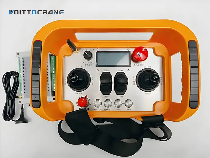
On peut mieux comprendre l'équipement électrique d'une grue comme étant composé de trois couches fonctionnelles qui fonctionnent ensemble : la couche de contrôle (comment les opérateurs commandent le mouvement), la couche d'alimentation et d'entraînement (comment les moteurs reçoivent et régulent l'électricité) et la couche de protection (comment le système arrête le mouvement en cas de problème).
La couche de contrôle : donner des ordres à la grue
La couche de commande regroupe tous les éléments avec lesquels l'opérateur interagit pour diriger les mouvements de la grue. Cela inclut les boîtiers de commande suspendus (panneaux à boutons-poussoirs câblés fixés à la passerelle de la grue), les systèmes de télécommande radio et, dans le cas des grues automatisées ou semi-automatisées, les automates programmables industriels (API).
Les boîtiers de commande à fil sont le système de commande le plus courant sur les ponts roulants et les ponts roulants standard. Ils fournissent des signaux de commande câblés directs pour la montée/descente du palan, le déplacement latéral du pont et le déplacement du chariot. Leur principal avantage réside dans leur simplicité et leur faible latence : la pression d'un bouton par l'opérateur se traduit directement par la commutation d'un relais ou d'un contacteur, sans dépendre d'un signal sans fil.
Les systèmes de radiocommande éliminent le câble de commande, offrant ainsi aux opérateurs une grande liberté de mouvement – un atout particulièrement précieux sur les portiques, les grues à flèche et les grues portuaires où l'opérateur peut avoir besoin de se repositionner fréquemment ou de maintenir une visibilité dégagée sur la charge. Un système de radiocommande performant pour grues industrielles couvre généralement une portée de 100 à 350 m, fonctionne dans une plage de températures allant de -35 °C à +80 °C et communique sur une bande de fréquence dédiée avec un codage anti-collision afin d'éviter les interférences entre plusieurs grues d'une même installation.
La commande par automate programmable est utilisée sur les ponts roulants de forte capacité, les systèmes de stockage automatisés et toute grue nécessitant des profils de mouvement séquentiels ou programmables. L'automate reçoit les signaux des codeurs, des capteurs de force et des interrupteurs de fin de course, puis transmet des commandes aux variateurs de fréquence et aux contacteurs. Point essentiel : l'automate interprète les signaux, il n'arrête pas physiquement le mouvement. L'arrêt physique est toujours assuré par le système de protection.
Couche de puissance et d'entraînement : régulation du fonctionnement des moteurs
Entre l'alimentation électrique et les moteurs de la grue se trouvent les équipements de commande et de commutation : contacteurs, variateurs de fréquence (VFD), relais de protection moteur et tableau électrique principal (armoire de commande). Cette couche détermine la fluidité des accélérations, des décélérations et du maintien de position de la grue.
Les contacteurs sont des interrupteurs électromécaniques qui ouvrent et ferment le circuit d'alimentation principal de chaque moteur. Ils constituent le lien physique entre une commande et le fonctionnement effectif du moteur. Sur un pont roulant standard, des contacteurs distincts commandent le moteur de levage, les moteurs de translation du pont et le moteur de translation du chariot ; leur dimensionnement est généralement déterminé en fonction du courant nominal et de la classe de service (classification FEM ou CMAA) du moteur.
Les variateurs de fréquence permettent aux moteurs d'accélérer et de décélérer progressivement, évitant ainsi les changements brusques de vitesse. Ceci présente deux avantages pratiques : une réduction des chocs mécaniques sur la structure de la grue (prolongeant la durée de vie des rails de roulement, des roues et des chariots d'extrémité) et une plus grande précision de positionnement de la charge. Sur les grues de grande capacité (généralement à partir de 10 tonnes), les variateurs de fréquence sont devenus la norme.
Les relais de protection moteur protègent contre la surchauffe et les surcharges de courant. Un relais de surcharge thermique surveille l'intensité du courant et coupe le circuit si le moteur dépasse sa capacité thermique nominale, évitant ainsi la destruction des enroulements. Sur les grues fonctionnant dans des environnements à cycles élevés (aciéries, chaînes de production automobile), cette protection est essentielle pour éviter les arrêts imprévus.
La couche de protection : garantir des limites de sécurité
La couche de protection est la partie du système électrique qui arrête la grue lorsqu'elle atteint une limite (positionnelle, liée à la charge ou à la température). Cette couche comprend des interrupteurs de fin de course, des dispositifs de protection contre les surcharges, des systèmes anticollision et des circuits d'arrêt d'urgence.
Interrupteurs de fin de course : types, fonction et importance de la mécanique
Un interrupteur de fin de course est un dispositif électromécanique qui coupe ou redirige un circuit électrique lorsqu'un composant de la grue atteint une position définie, évitant ainsi les dépassements de course, les blocages, les collisions en bout de voie et les surcharges du moteur.
Les types les plus couramment utilisés dans les applications de grues sont :
- Interrupteurs de fin de course rotatifs (à cames) — monté sur l'arbre du tambour de levage ; mesurer la position de rotation pour respecter les limites de course du crochet supérieur et inférieur
- Interrupteurs de fin de course linéaires (à levier/à galet) — montés aux extrémités des pistes ou aux limites de déplacement des chariots ; actionnés par contact physique avec un percuteur
- Interrupteurs de fin de course à gravité (à poids) — installé sur le câble de levage ; déclenchement lorsque le crochet atteint une position dangereusement haute
- Interrupteurs de proximité magnétiques — Détection sans contact utilisant des cibles magnétiques ; utilisée lorsque l’usure physique des actionneurs est un problème
Pourquoi les interrupteurs de fin de course rotatifs sont la principale protection des palans
Le fin de course rotatif est le premier et le plus important dispositif de protection électrique de tout mécanisme de levage. Il est fixé à l'arbre du tambour et utilise un système de cames interne pour compter précisément le nombre de tours effectués par le tambour et déterminer la position du crochet. Lorsque le crochet atteint sa limite supérieure prédéfinie, la came tourne pour ouvrir le circuit et couper l'alimentation du moteur du palan.
Cette conception est cruciale car son positionnement est absolu : elle est indépendante des signaux de l’encodeur, du logiciel de l’automate programmable et du temps de réaction de l’opérateur. Même en cas de panne de l’automate programmable ou de commande erronée du variateur de fréquence, le fin de course rotatif interrompt physiquement le circuit. Sur les ponts roulants bipoutres de grande capacité, manipulant des charges supérieures à 20 tonnes, un fin de course rotatif correctement réglé fait toute la différence entre un arrêt contrôlé et un blocage brutal – où le crochet entre en contact avec le carter du tambour, risquant de rompre les câbles et de provoquer la chute de la charge.
Limite supérieure et limite ultime : une distinction cruciale
Les systèmes de levage de grues bien conçus comportent deux limites supérieures au lieu d'une seule. La première, la limite supérieure de travail, ralentit la vitesse de levage lorsque le crochet approche de sa hauteur de course maximale, réduisant ainsi l'impact mécanique lors du freinage. La seconde, la limite supérieure ultime (ou de secours), est légèrement plus élevée et s'active uniquement en cas de défaillance ou de mauvaise configuration de la limite supérieure de travail. Après son déclenchement, une réinitialisation manuelle et une inspection sont généralement nécessaires avant que la grue puisse reprendre son fonctionnement normal. Cette architecture à deux niveaux est décrite dans la norme ASME B30.2 et constitue la norme pour les grues destinées aux marchés européens, conformément à la norme EN 13135.
Interrupteurs de fin de course pour le mouvement des ponts et des chariots
Sur les ponts roulants, les portiques et les ponts roulants, des interrupteurs de fin de course à levier ou à galet sont installés aux extrémités du chemin de roulement et aux butées de course du chariot. Ces interrupteurs empêchent le pont ou le chariot de heurter les butées à vitesse de fonctionnement. Sur les ponts roulants de grande portée ou pour les applications à grande vitesse, le système de limitation de course est souvent configuré en deux étapes : une butée de décélération qui provoque une réduction de vitesse, suivie d’une butée d’arrêt.
Dispositifs de sécurité : protection contre les surcharges, système anti-collision et arrêt d’urgence
Au-delà des interrupteurs de fin de course, un système électrique complet de grue comprend plusieurs dispositifs de sécurité supplémentaires qui forment collectivement l'enveloppe de protection de la grue.
Limiteurs de charge et protection contre les surcharges
Un limiteur de charge (également appelé relais de protection contre les surcharges ou système de capteurs de pesage) contrôle la charge réelle sur le crochet et empêche le levage si le poids dépasse la capacité nominale de la grue. Sur les grues plus simples, cette fonction est assurée par un embrayage limiteur de couple ou un relais de détection de courant qui se déclenche à un seuil de surcharge défini. Pour les applications de précision — entrepôts automatisés, stockage d'acier en grande hauteur, maintenance nucléaire —, des capteurs de pesage fournissent un retour d'information continu sur le poids à l'automate programmable, permettant une gestion dynamique de la charge et un enregistrement des opérations.
Les limiteurs de charge sont indispensables sur les grues de qualité. La plupart des normes internationales, notamment l'ISO 9927-1 pour l'inspection des grues et l'EN 13001 pour leur conception, exigent une protection contre les surcharges démontrable. Dans le cadre d'un achat, demander un certificat d'essai de charge en usine confirmant le seuil de déclenchement en cas de surcharge est une pratique courante et raisonnable.
Systèmes anticollision
Dans les installations exploitant plusieurs ponts roulants sur une même voie de circulation — une configuration courante dans les aciéries, les usines d'assemblage automobile et les parcs à béton préfabriqué —, des systèmes anti-collision empêchent deux ponts roulants de s'approcher au-delà d'une distance de sécurité minimale. Ces systèmes utilisent des capteurs de proximité, des télémètres laser ou des détecteurs à ultrasons pour mesurer en continu la distance entre les ponts roulants et ralentir ou arrêter automatiquement le pont roulant qui s'approche avant tout contact.
Le système anticollision est particulièrement important sur les ponts roulants bipoutres à grande portée, où, à vitesse de fonctionnement, une grue peut parcourir une distance plus rapidement que l'opérateur ne peut réagir. La présence d'un système anticollision doit être explicitement spécifiée dans le bon de commande et ne pas être considérée comme standard.
Circuits d'arrêt d'urgence
Chaque grue doit être équipée d'au moins un arrêt d'urgence (arrêt E) qui coupe immédiatement et indépendamment du circuit de commande normal. Sur les grues à commande par pendentif, l'arrêt d'urgence est généralement un bouton-poussoir situé sur le pendentif. Sur les grues radiocommandées, un canal d'arrêt d'urgence dédié doit être mis en œuvre, distinct des commandes normales, et doté d'une conception à sécurité intégrée : en cas de perte de la liaison radio, la grue doit s'arrêter automatiquement au lieu de poursuivre son fonctionnement.
Que vérifier auprès de votre fournisseur avant d'accepter une configuration électrique
Lors de l'acquisition d'une grue — qu'il s'agisse d'un pont roulant, d'un portique, d'un pont roulant ou d'un palan électrique — les spécifications du système électrique méritent la même attention que celles de la structure mécanique.
Questions clés à soulever lors de l'établissement du devis :
- Quel type de système de commande est fourni : boîtier de commande, télécommande radio ou automate programmable ? La fréquence de la télécommande radio est-elle conforme à la réglementation en vigueur dans votre pays ?
- Les interrupteurs de fin de course sont-ils mécaniques (à came, à levier) ou à détection de proximité ? Le palan est-il configuré avec une double limite (de travail + limite ultime) ?
- Quel dispositif de protection contre les surcharges est installé : relais de courant, limiteur de couple ou système de cellule de charge complet ?
- Le tableau électrique est-il conçu selon la norme IP54 ou supérieure pour les environnements poussiéreux ou humides ?
- À quelles normes de conformité le système électrique répond-il — IEC 60204-32 (équipements électriques des machines), EN 13135 (composants électriques et hydrauliques des grues européennes) ou CMAA 70/ASME B30.2 pour les marchés nord-américains ?
Demander la déclaration de conformité CE, le schéma électrique et le rapport d'essai en usine pour les réglages des interrupteurs de fin de course avant l'expédition est une pratique courante et fournit à votre équipe la documentation nécessaire aux inspections des autorités locales.
Conclusion
L'équipement électrique de la grue — comprenant les systèmes de commande, les interrupteurs de fin de course et les dispositifs de protection — est le système qui détermine si une grue, même structurellement capable, fonctionne en toute sécurité. La compréhension des trois niveaux fonctionnels (commande, alimentation/entraînement, protection) offre aux équipes d'approvisionnement un cadre clair pour évaluer les propositions des fournisseurs, plutôt que d'accepter une configuration générique.
Lors de la spécification ou de la vérification d'une commande de grue, assurez-vous de la conformité de l'architecture des interrupteurs de fin de course, du système de protection contre les surcharges et du type de système de commande avec l'environnement opérationnel de votre installation et les normes applicables. Pour plus d'informations sur les équipements électriques pour grues proposés par Voitto Crane, notamment les systèmes de télécommande, veuillez contacter directement leur équipe.

Alan
Spécialiste des solutions de grue · Voitto Crane
Spécialisé dans les solutions d'exportation de ponts roulants, de portiques, de grues à flèche, de grues portuaires et de grues EOT. Plus de 10 ans d'aide aux clients internationaux en matière de consultation avant la vente, de sélection de la capacité et de configurations spécifiques au site.
FAQ
Q1 : Quelle est la différence entre un interrupteur de fin de course supérieur et un interrupteur de fin de course ultime sur un palan de grue ?
Le capteur de fin de course supérieur est le principal dispositif d'arrêt : il arrête ou ralentit le mouvement du palan lorsque le crochet atteint sa hauteur de déplacement maximale en cas de sécurité, en fonctionnement normal. Le capteur de fin de course ultime est un dispositif secondaire, de secours, situé légèrement au-dessus du capteur de fin de course supérieur. Il s'active uniquement en cas de défaillance ou de mauvais réglage de ce dernier, et nécessite généralement une réinitialisation manuelle avant que la grue puisse reprendre son fonctionnement. L'action combinée de ces deux capteurs empêche le blocage complet, situation dangereuse où le crochet entre en contact avec le carter du tambour.
Q2 : Un automate programmable de grue peut-il remplacer les interrupteurs de fin de course mécaniques pour les fonctions de sécurité ?
Non, un automate programmable peut surveiller et gérer les mouvements d'une grue, mais il ne peut remplacer les interrupteurs de fin de course mécaniques comme dispositifs de sécurité. Un automate programmable interprète les signaux et émet des commandes ; en cas de défaillance d'un capteur ou d'erreur de programme, il risque de ne pas arrêter correctement le mouvement. Les interrupteurs de fin de course mécaniques ouvrent physiquement le circuit, indépendamment de l'état du logiciel. C'est pourquoi des normes telles que la CEI 60204-32 et la norme EN 13135 exigent une protection mécanique indépendante en complément de toute commande logicielle.
Q3 : Quel indice de protection IP doivent avoir les panneaux électriques et les interrupteurs de fin de course des grues dans les environnements industriels intérieurs ?
Pour les environnements intérieurs standard modérément poussiéreux (ateliers, entrepôts), l'indice de protection IP54 est généralement le minimum requis pour les armoires électriques et les interrupteurs de fin de course. Dans les environnements fortement poussiéreux, exposés aux projections d'eau ou aux vapeurs chimiques (aciéries, cimenteries, portiques extérieurs, installations portuaires), un indice de protection IP65 ou IP67 est recommandé. Il est impératif de toujours vérifier l'indice de protection IP de tous les composants électriques auprès de votre fournisseur et de l'adapter aux conditions réelles du site, plutôt que de supposer qu'une utilisation en intérieur implique un environnement propre.
Q4 : Quelles sont les normes qui régissent les équipements électriques des grues sur les marchés européens et internationaux ?
Les normes essentielles sont la CEI 60204-32 (équipements électriques des grues et palans), la norme EN 13135 (composants électriques et hydrauliques utilisés sur les grues) et la norme EN 13001 (conception des grues, incluant les exigences relatives aux dispositifs de sécurité). Pour les grues portant le marquage CE et destinées au marché de l'UE, la conformité à la directive Machines 2006/42/CE est obligatoire, et le système électrique constitue un élément clé de l'évaluation de la conformité. Demandez la déclaration de conformité CE et vérifiez expressément si les composants électriques – et non seulement la structure – sont couverts par la certification.
Q5 : À quelle fréquence faut-il inspecter les interrupteurs de fin de course des grues ?
Les interrupteurs de fin de course doivent être vérifiés quotidiennement avant la mise en service de la grue : une inspection visuelle et un test fonctionnel confirment leur bon déclenchement. Une inspection plus approfondie, incluant la vérification de l’état des contacts, de l’usure de l’actionneur et du calibrage du point de déclenchement, doit être effectuée mensuellement ou selon le calendrier de maintenance du fabricant de la grue, la fréquence la plus élevée étant retenue. Les interrupteurs de fin de course s’usent avec le temps en raison de l’accumulation de cycles mécaniques ; le suivi du nombre de cycles et le remplacement préventif des interrupteurs permettent d’éviter les coûts bien plus importants d’un incident de grue dû à une défaillance d’interrupteur.




 English
  Español
  Português
  العربية
  Français
  Русский